
Smart systems and connected devices
A smart crossroads with the micro:bit - from the LED screen to two traffic lights that talk to each other
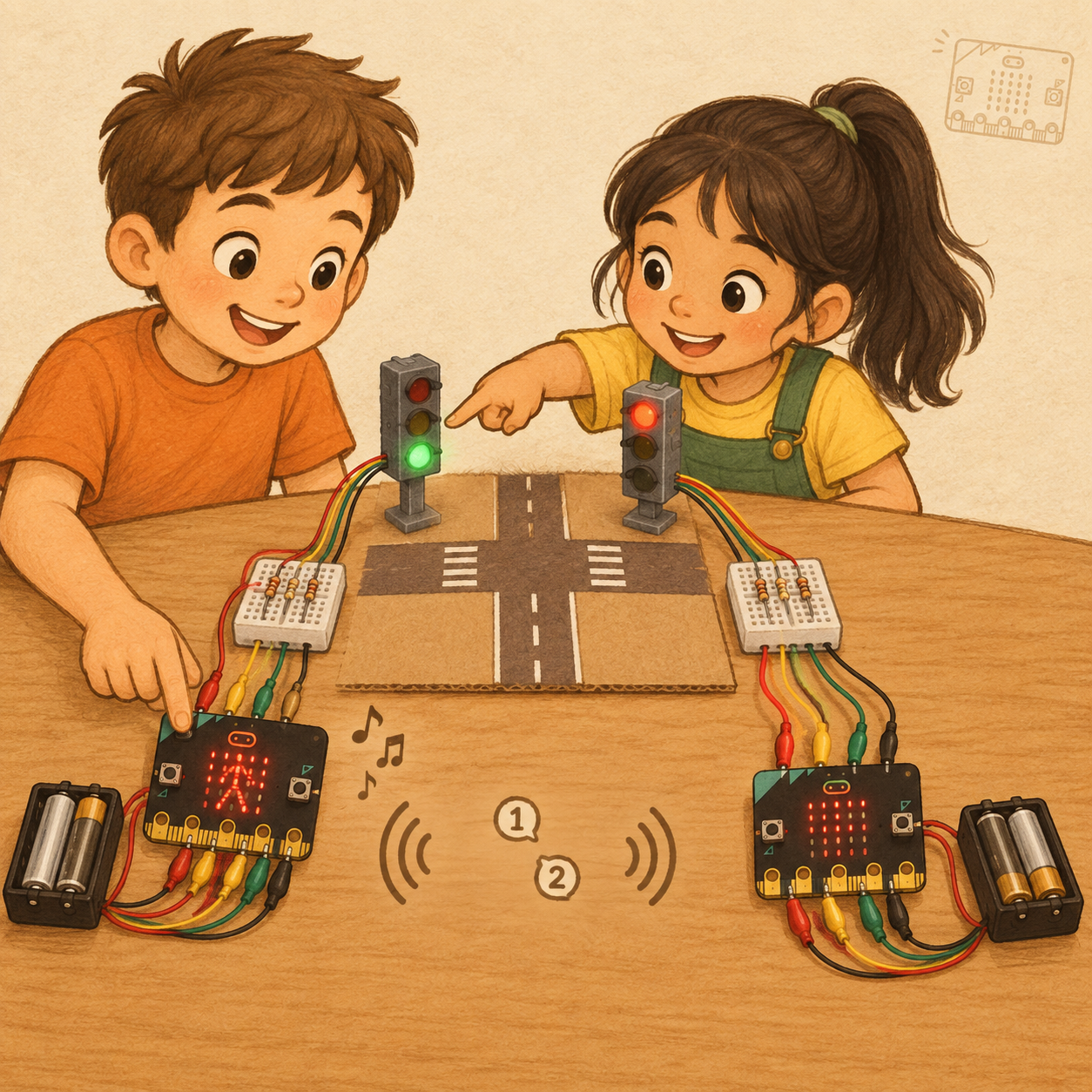
Now we are going one step further.
We won’t just make a program that runs on one micro:bit any more. We will build smart devices that can control real lights, sound, sensors, motors and other parts of our models.
We will learn how one micro:bit can:
- switch on a real LED;
- control a traffic light;
- notice what is happening around it;
- send a message to another micro:bit;
- receive a message and react to it;
- work together with another device as part of a bigger system.
Imagine a traffic light at a crossroads. It isn’t just a set of lights. It has to know when the other direction is red, when pedestrians may cross and how to send a clear message to the people who are waiting.
That is an example of a smart system.
A smart system has several important parts:
Input ⇒ the program decides ⇒ output ⇒ communication with other devices
For example, at our crossroads today:
- A button or a radio message
- The micro:bit program decides what state the crossroads is in
- The traffic light switches between red, yellow and green
- The LED screen shows the signal for pedestrians
- A sound sends an extra message to people with poor eyesight
From today, we will think like a team building a real device:
- What should our device do?
- What information does it need?
- How will it show the result?
- What happens when it works together with another device?
- How will we check that it doesn’t make a mistake?
The most important rule stays the same:
First we make one small thing work. Then we test it. Only then do we add the next part.Today we start with a smart crossroads – our first project in which our micro:bits will light up, communicate and work together.
A smart crossroads with the micro:bit
Today we will build a small smart crossroads.
First we will show a traffic light on the micro:bit’s built-in LED screen. Then we will move the same logic to our 3D-printed traffic light model with real LEDs. After that we will connect two traffic lights by radio, add a pedestrian light on the LED screen and, finally, add sound to help people with poor eyesight.
Our crossroads won’t be a real traffic system. It is an educational model that helps us learn:
- how a program controls a light;
- how the micro:bit sends a signal to external LEDs;
- how two micro:bits exchange messages;
- how one device can show information in several ways: with light, a picture and sound.
The most important rule of our crossroads: two directions must never have a green light at the same time.
Our mission
By the end of the workshop, each pair will have:
- two 3D-printed traffic lights;
- two micro:bits;
- two directions at the crossroads;
- external red, yellow and green LEDs on each model;
- the micro:bit LED screen showing a pedestrian light;
- radio messages that keep both traffic lights in step;
- a short sound signal when pedestrians get the signal to cross.
Our system goes through several states
| Step | State | Traffic light A | Traffic light B | Pedestrians at A | Pedestrians at B |
|---|---|---|---|---|---|
| 1 | Safety state before direction A | red | red | stand | stand |
| 2 | Direction A gets ready | red + yellow | red | stand | stand |
| 3 | Direction A goes | green | red | walk | stand |
| 4 | Direction A gives a warning | green flashes | red | stand | stand |
| 5 | Direction A stops | yellow | red | stand | stand |
| 6 | Safety state before direction B | red | red | stand | stand |
| 7 | Direction B gets ready | red | red + yellow | stand | stand |
| 8 | Direction B goes | red | green | stand | walk |
| 9 | Direction B gives a warning | red | green flashes | stand | stand |
| 10 | Direction B stops | red | yellow | stand | stand |
| ⇒ | Back to the start | red | red | stand | stand |
For our educational model we use a simple rule:
- Vehicles green ⇒ pedestrians in the same direction walk.
- Vehicles green flashing ⇒ pedestrians in the same direction stand.
- Vehicles yellow ⇒ pedestrians in the same direction stand.
- Vehicles red + yellow ⇒ pedestrians in the same direction stand.
- Vehicles red ⇒ pedestrians in the same direction stand.
In real towns and cities, traffic lights can have more rules, special times for pedestrians, sensors for cars and extra safety phases. Today we are building a simpler model so that we can understand the basic logic.
What we use
Each pair gets:
- 2 × micro:bit V2 – The programmable “brains” of the traffic lights
- 2 × 3D-printed traffic light – Models with real LEDs
- 2 × mini breadboard – A place for the resistors and connections
- 2 × battery pack – Power for the micro:bit after programming
- Crocodile clips – Connect the micro:bit, the breadboard and the traffic light model
- 6 × resistor – Each LED needs its own resistor
- Wires from the model – Red, yellow, green and a shared black wire
On the micro:bit V2 we will also use the built-in LED screen and the built-in speaker.
Connecting the traffic light safely
Our 3D-printed models have four wires:
- Red: Connected to the red LED
- Yellow: Connected to the yellow LED
- Green: Connected to the green LED
- Black: The shared GND wire for all the LEDs
Each LED must have its own resistor. The red, yellow and green LEDs don’t share one resistor. The resistors aren’t inside the 3D-printed model. We put them on the mini breadboard.
The layout we have agreed on is:
- micro:bit P0 ⇒ resistor ⇒ red wire of the traffic light
- micro:bit P1 ⇒ resistor ⇒ yellow wire of the traffic light
- micro:bit P2 ⇒ resistor ⇒ green wire of the traffic light
- micro:bit GND ⇒ shared black wire of the traffic light
A micro:bit digital pin can send the state 1 to switch a signal on or 0 to switch it off. In MakeCode we use this to switch external LEDs on and off.
Digital signals and the micro:bit's pins
The micro:bit doesn't always have to send a complicated message. Sometimes a very simple decision is enough: ON (1) or OFF (0).
We call a message like this a digital signal.
A digital signal has only two states:
- 1 = On / HIGH; the LED can light up
- 0 = Off / LOW; the LED is off
On the micro:bit we use pins – the small metal contacts along the bottom edge of the board – to send a digital signal to an external device. The micro:bit has lots of pins, and for our traffic light we use P0, P1 and P2.
The rule before connecting
- The battery pack must be switched off.
- We connect the wires and the resistors.
- We check the connections.
- The leader checks the circuit.
- Only then do we switch on the power and test.
We never connect an LED straight to a pin without a resistor.
Exercise 1: A traffic light on the LED screen
Before the real model, we will make a traffic light on the micro:bit’s built-in LED screen.
The micro:bit has a small screen of 5 × 5 LEDs. In MakeCode we can use the show leds block and draw our own pictures. The LED dots that are lit make a symbol, a picture or a message.
A traffic light you control by hand
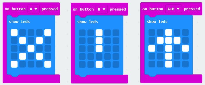
Let’s make three simple pictures:
- Button A = red: STOP
- Button B = yellow: GET READY
- Buttons A+B = green: GO
We can use these symbols:
- Red: X
- Yellow: !
- Green: ↑
Or we can draw our own pictures with the show leds block.
What are we learning here?
- Button = input
- LED screen = output
When we press a button, the micro:bit receives information. Then the program decides which picture to show on the LED screen.
Quiz 1: The LED screen and events
1. What is the input in our hand-controlled micro:bit traffic light?
2. What is the output in the first part of the exercise?
3. Why do we make the traffic light on the LED screen first, and not straight away on the real model?
Exercise 2: The green light flashes
Now we will add an important warning.
Before the green light changes to yellow, the green light will flash for a short time. The flashing tells drivers that the state is about to change.
The flashing plan:
- Switch green on (1)
- Wait
- Switch green off (1)
- Wait
- Switch green on (2)
- Wait
- Switch green off (2)
- Show yellow
- Wait a little longer
To start with, let green flash two or three times.
In MakeCode we will use:
- pause to wait,
- repeat to flash a set number of times,
- forever to keep repeating the whole traffic light cycle.
- pause says how long we wait.
- repeat says how many times we repeat the same action.
- forever says that we keep repeating the whole cycle.

Extra challenge
Change the waiting time when the light flashes:
- 100 ms = a tenth of a second
- 1000 ms = one second
Which kind of flashing looks better: faster or slower?
Quiz 2: Flashing and time
4. What does it mean when the green light flashes?
5. What is the pause block for?
6. How long is 1000 ms?
7. What is the difference between repeat and forever?
Exercise 3: A real 3D-printed traffic light
Now we move the logic from the LED screen to the real model.
The micro:bit won’t just show a symbol on its own screen any more. Now it will use its pins to control real LEDs in the 3D-printed traffic light.
Connecting
First disconnect the micro:bit from the computer and from the batteries (if you are using them).
Then connect:
- P0 ⇒ resistor ⇒ red wire
- P1 ⇒ resistor ⇒ yellow wire
- P2 ⇒ resistor ⇒ green wire
- GND ⇒ black wire
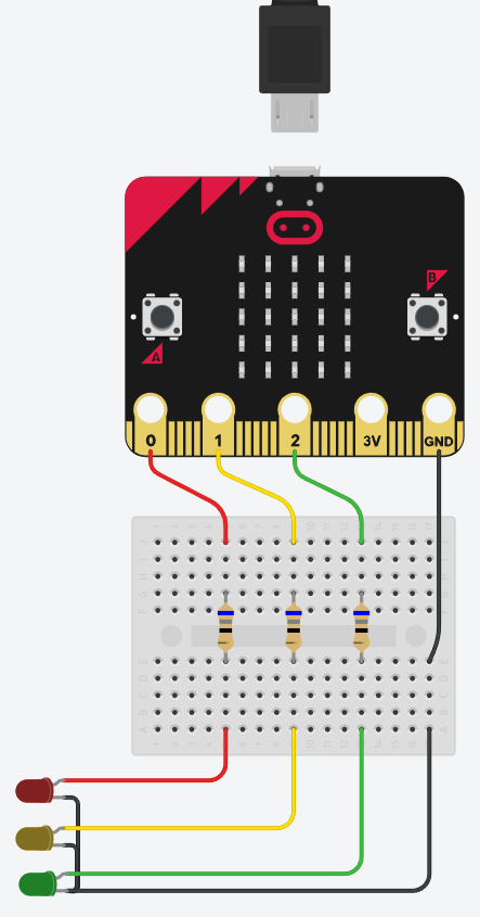
Why do we use these particular wire colours?
After connecting, check:
- The black wire is on GND.
- The red LED has its own resistor.
- The yellow LED has its own resistor.
- The green LED has its own resistor.
- The crocodile clips aren’t touching each other.
- The wires aren’t pulled too tight.
- The leader has checked the connections.
Colour test
Before the automatic traffic light, we check each colour separately:
- Button A ⇒ switch on only the red light
- Button B ⇒ switch on only the yellow light
- Buttons A+B ⇒ switch on only the green light
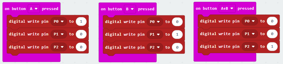
When we switch one colour on, the other two should be off.
If pressing button A switches on the green LED instead of the red one, we don’t change the whole program straight away. First we check:
- whether the red wire really is connected to P0;
- whether the wire has been mixed up with another colour;
- whether the resistor is in the right place;
- whether the shared black wire is on GND.
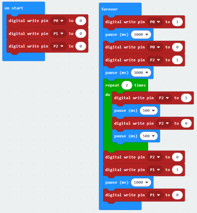
Moving the automatic cycle across
After testing, we use the pins instead of the LED screen:
- Red:
- P0 = 1
- P1 = 0
- P2 = 0
- Yellow:
- P0 = 0
- P1 = 1
- P2 = 0
- Green:
- P0 = 0
- P1 = 0
- P2 = 1
To make the green light flash, we repeat:
- P2 = 1
- wait
- P2 = 0
- wait
This way the same program idea controls a real light, not just a picture on the screen.

Quiz 3: External LEDs
8. Why does each LED in the traffic light need its own resistor?
9. Where do we connect the traffic light's shared black wire?
10. What do we do first, before we move a wire or a resistor on the breadboard?
11. What should we check if button A switches on the green LED instead of the red one?
Exercise 4: Two traffic lights talk by radio
Now each pair has two micro:bits and two traffic lights:
- Traffic light A controls one direction of the road.
- Traffic light B controls the other direction.
The traffic lights need to know when the other direction has green.
The micro:bits can send short radio messages without any wire between them.
Radio group
For two micro:bits to talk to each other, they must be in the same radio group.
Pair 1 ⇒ radio group = 41
Pair 2 ⇒ radio group = 42
Pair 3 ⇒ radio group = 43
Pair 4 ⇒ radio group = 44
Only micro:bits with the same group number should react to each other. A radio group can have a value from 0 to 255.
First we test the radio without the traffic lights
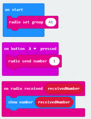
If the second micro:bit shows the number 1, the radio link works.
Only then do we connect the radio message to the real traffic lights.
Agreeing on the messages
Both micro:bits need to know what each number means:
- 0 = Both traffic lights are red
- 1 = Traffic light A is red and yellow, traffic light B is red
- 2 = Traffic light A is green, traffic light B is red
- 3 = Traffic light A flashes green, traffic light B is red
- 4 = Traffic light A is yellow, traffic light B is red
- 5 = Traffic light A is red, traffic light B is red and yellow
- 6 = Traffic light A is red, traffic light B is green
- 7 = Traffic light A is red, traffic light B flashes green
- 8 = Traffic light A is red, traffic light B is yellow
The number 2 doesn’t mean green on its own. We agreed that message 2 means this state.
Notice: after message 4 comes the phase in which both traffic lights are red. It doesn’t have its own number because it is the same as the state for message 0, so we use the number 0 again.
The most important test
For each radio message, we check both models:
- If traffic light A shows green,
- traffic light B must show red.
- If traffic light B shows green,
- traffic light A must show red.
No message may give a green light on both traffic lights at the same time.Can both traffic lights be red at the same time?
From now on, each micro:bit is programmed separately.
The micro:bits don't have the same job:
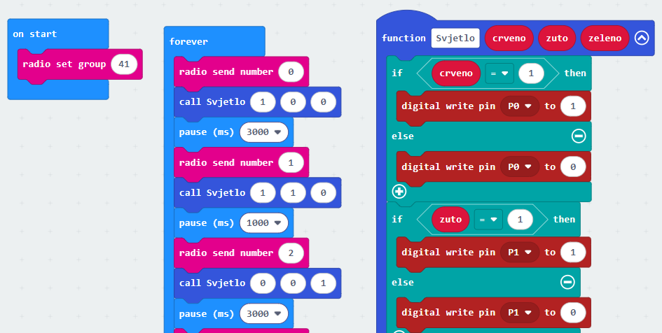
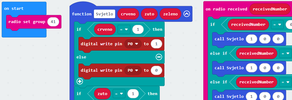
One micro:bit is in charge of the traffic lights, and the other listens to the messages it receives and acts on them.What is a function?
A function is a group of blocks that we give a name. When we need it, we don't put all those blocks together again; we just call the function by its name with the call block.
A function is like a recipe: we write it down once, and then we can cook from it as many times as we like.
Our function is called Svjetlo (Croatian for "light"). When we call it, we give it three numbers, for the red, yellow and green lights, in the same order as the lights on the traffic light, from top to bottom. In the code they are called crveno, zuto and zeleno (red, yellow and green). We call these numbers parameters:
- 0 = the light is off
- 1 = the light is on
- 2 = the green light flashes
For example, call Svjetlo 1 1 0 means: red on, yellow on, green off.
Why do we use a function here?
- For each state of the traffic light we have to set all three pins: P0, P1 and P2. Without a function, we would have to put the same digital write pin blocks together again for every state.
- The program is shorter and easier to read. The call call Svjetlo 0 0 1 shows straight away which light is on, just like a row in the state table.
- If we change something, for example the pin for a colour or how fast the light flashes, we only change it in one place.
- Both micro:bits use the same function. Traffic light A and traffic light B switch their lights on in the same way; the only difference is when they call it.
The micro:bit in charge (the main one) Traffic light A:
The micro:bit that listens Traffic light B:
Quiz 4: The radio link
12. What do two micro:bits need so that they can talk to each other by radio?
13. Why does each pair get its own radio group?
14. Why do we test the radio first by showing the received number on the LED screen?
15. Can both traffic lights show green at the same time?
Exercise 5: A pedestrian light on the LED screen
The external 3D-printed model shows the lights for vehicles. We use the micro:bit’s built-in LED screen as the light for pedestrians.
We will make two pictures:
- A person standing ⇒ pedestrians wait
- A person walking ⇒ pedestrians can cross
Pedestrian standing
You can draw a picture like this in the show leds block:
. . # . .
. # # # .
. . # . .
. # . # .
. # . # .
Pedestrian walking
You can draw a picture like this:
. . # . .
# # # # .
. . # . .
. # . # .
# . . # #
It doesn’t have to look exactly the same. What matters is that you can tell the difference between a person standing and a person walking.
The pedestrian rule
On one micro:bit:
- If vehicles have green:
- the pedestrian walks
- If vehicles have flashing green:
- the pedestrian stands
- If vehicles have yellow:
- the pedestrian stands
- If vehicles have red:
- the pedestrian stands
This way one micro:bit controls two different outputs:
- External LEDs ⇒ the traffic light for vehicles
- LED screen ⇒ the light for pedestrians
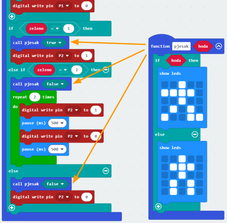
If you look at the rule above, you will see that the pedestrian only walks when the green light is on all the time. That means we can add this behaviour to our earlier code (from exercise 4) as a call to the function pjesak (Croatian for “pedestrian”), and only in the part of the code that deals with the green light (the zeleno parameter):
- If green is on (value 1):
- The pedestrian walks
- Otherwise (value 0 or 2):
- The pedestrian stands.
The function’s parameter is called hoda (“walks”): true means the pedestrian walks, and false means the pedestrian stands.
Quiz 5: The pedestrian light
16. What does the micro:bit's LED screen show in this exercise?
17. What should the pedestrian light show when vehicles in the same direction have green?
18. What can the pedestrian light show when vehicles in the same direction have red?
Exercise 6: Sound to help pedestrians
Now we add sound.
A question to think about:How can a person who can't see the traffic light find out that it is safe to cross the road?
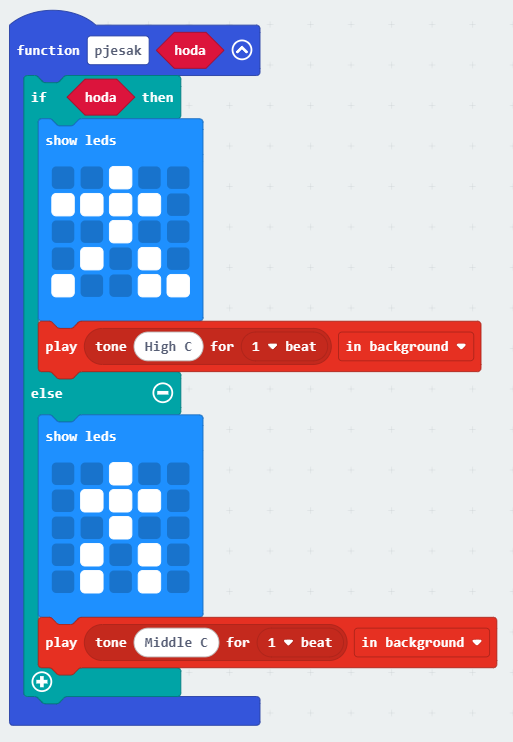
The MakeCode block play tone can play a tone of a certain pitch and length. We set the tone with a frequency and a time in milliseconds. We will use the in background option, so that playing the sound doesn’t get in the way of the traffic light working normally.
The sound rule in the workshop
- We test the sound briefly.
- We don't play a tone non-stop for the whole green state.
- When several pairs are working, we test the sound when the leader gives the signal.
A good device can send a message in several ways: with light, a picture and sound.
Task: Add suitable sounds to the pjesak function.
Final challenge: Show your crossroads
Each pair shows one full traffic cycle.
Before you show it, check:
- Both traffic lights use the same radio group within the pair.
- Different pairs use different radio groups.
- Each LED has its own resistor.
- No crocodile clips are touching each other.
- The LED screen can be seen.
- At no moment is there a green light on both traffic lights.
Check that everything works as shown in the traffic light state table.
 What did we learn?
- The micro:bit can control its built-in LED screen and real external LEDs.
- The micro:bit’s buttons can be inputs, and the LED screen and external LEDs can be outputs.
- A green light can flash by switching the LED on and off again and again.
- pause sets how long the program waits.
- repeat repeats an action a set number of times, and forever keeps repeating the program.
- Each external LED needs its own resistor.
- The shared black wire of our traffic light is connected to GND.
- Pins P0, P1 and P2 can control the red, yellow and green LEDs.
- Two micro:bits can exchange radio messages when they use the same radio group.
- Different pairs use different radio groups so that their traffic lights don’t get in each other’s way.
- Radio messages must have a meaning that has been agreed in advance.
- A pedestrian light can be shown on the micro:bit’s LED screen.
- In our model, pedestrians walk when vehicles in the same direction have a steady green light.
- Sound can help people with poor eyesight find out that the state has changed.
- Two directions at a crossroads must never have a green light at the same time.