
Breadboard lab
How do we build an electronic circuit without soldering?
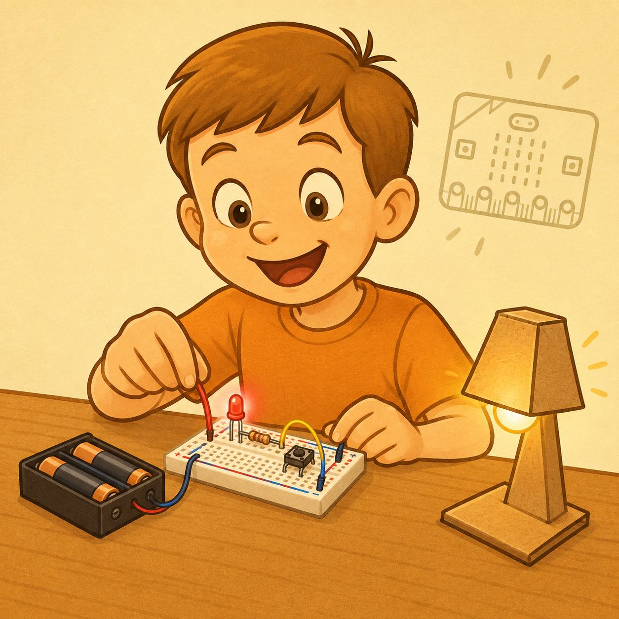
In the first workshop we made our first circuit and lit up an LED. In the second one we became electricity detectives and found out which materials conduct electricity.
Today we will meet one of the most important tools for inventors, electronics engineers and robot builders: the breadboard.
A breadboard is a small plastic board with lots of holes. At first it may look like an ordinary board full of dots, but underneath it there are hidden metal connections. These connections help us build an electronic circuit without soldering.
This means we can:
- Add and remove parts.
- Move wires around.
- Try out new ideas.
- Find and fix mistakes.
- Take the project apart when we are finished.
Today we will build an LED light on a breadboard and learn how a push button can switch a light on.
Our mission
Your task is to build a small circuit in which the LED only lights up while you are pressing the push button.
Our circuit path can look like this:
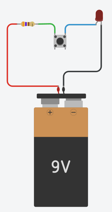
When the push button isn’t pressed, the circuit is open and the LED doesn’t light up.
When we press the push button, the circuit closes and the LED can light up.
A push button is a small switch that only closes the circuit while we keep it pressed.
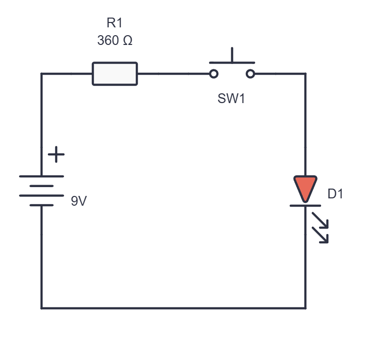
The circuit diagram (schematic) of our circuit looks like this:
What is a breadboard?
A breadboard is a board for trying out electronics.
We can put LEDs, resistors, wires, push buttons and sensors on it. We don’t use a soldering iron, so we can easily change our project if we want to try something new.
A breadboard is like a big LEGO baseplate, but for electronic parts:
- LEGO baseplate ⇒ we connect bricks
- Breadboard ⇒ we connect electronic parts
A breadboard helps us make a prototype.
A prototype is the first test version of an invention. It helps us check whether an idea works before we make the final project.
The secret under the holes
The holes on a breadboard are not all separate.
Under the plastic there are small metal strips. They connect certain holes together, so electric current can travel between them.
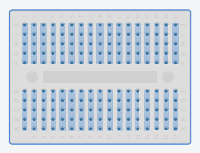
Most breadboards have these main parts:
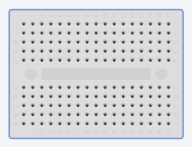
- Two central areas with lots of holes and a gap in the middle. This is where we put LEDs, resistors, push buttons and wires.
- The red line (or the + sign) brings plus from the battery to different parts of the circuit.
- The blue or black line (or the − sign) brings minus from the battery to different parts of the circuit
The red and blue lines are not on the mini breadboard that we will often use.
Each central area has lots of groups of five connected holes (see the picture above).
If you put a wire into one hole of a group, it is electrically connected to the other four holes in the same group.
On the other side of the middle gap there is another group of five holes, but the two sides are not automatically connected to each other.
Rule to remember
Five holes on the same side are often connected, but the middle gap breaks the connection between the two sides.You can read more about bigger breadboards here: Electronic components, symbols and diagrams.
The parts of our circuit
Today we are using a few parts:
- Breadboard – the place where we build the electronic circuit
- Battery holder – gives energy to the circuit
- Jumper wires – connect different parts of the breadboard
- LED – turns electrical energy into light
- Resistor – protects the LED from too much current
- Push button – opens and closes the circuit
The LED has two legs and they are not the same:
- The longer leg usually goes towards plus.
- The shorter leg usually goes towards minus.
- The flat side on the rim of the LED shows the side of the shorter leg.
An LED has a direction. If we put it in the wrong way round, it usually won’t light up.
A resistor has no plus or minus. We can turn it either way round.
- The resistor’s job is to limit the amount of current that flows through the LED.
Rule to remember
An LED has a direction, a resistor has no direction, and an LED always needs a resistor.An LED must not be connected straight to the power supply without a resistor, because too much current can damage the component.
A push button is a small switch.
- When the push button isn’t pressed, the circuit is open.
- When we press the push button, it closes the circuit.
- When the circuit is closed, the LED can light up.
- A push button often has four legs. That is why we usually place it across the middle gap of the breadboard. This way the legs of the push button are separated properly and it can work as a switch.
Before you build
- Before you start building the circuit, get your workbench ready.
- Put only the parts you need on the table.
- Find the plus and minus on the battery holder.
- Find the red and black wires with the crocodile clips.
- Look at the LED and find the longer and shorter legs.
- Find the resistor and the push button.
- Check that the battery holder is switched off.
The most important rule
Always switch off the power (the battery) before moving wires.How to build our circuit
Follow the steps slowly. After each step, look at your breadboard and compare it with the example the leader shows you:
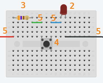
Step 1: Check that the battery is switched off.
Step 2: Place the LED
- Carefully spread the legs of the LED apart.
- Place the LED on the right-hand side of the breadboard, so that its two legs are not in the same connected group of holes. (see the picture)
- The longer leg should be on the side that will be connected towards plus.
- The shorter leg should be on the side that will be connected towards minus.
- If you put both legs of the LED into the same connected group of holes, the LED won’t be connected properly.
Step 3: Add the resistor
- Place the resistor on the left-hand side of the breadboard, so that its two legs are not in the same connected group of holes. (see the picture)
The resistor protects the LED and helps it light up safely.
Step 4: Place the push button
- Place the push button across the middle gap of the breadboard.
- Connect one side of the push button with a wire to the right leg of the resistor.
- Connect the other side of the push button with a wire to the longer leg of the LED.
Now the main part of our circuit is ready:
Step 5: Connect the wires
- Plug the red wire (the one with a crocodile clip on one end) into the group of holes with the left leg of the resistor.
- Plug the black wire (the one with a crocodile clip on one end) into the group of holes with the shorter leg of the LED.
- Use the green wire to connect the group of holes with the right leg of the resistor to the group with the left leg of the push button.
- Use the blue wire to connect the group of holes with the right leg of the push button to the group with the longer leg of the LED.
Step 6: Check before switching on
Before you connect the battery, check the following:
- Is the battery’s red wire on the resistor?
- Is the battery’s black wire on the LED?
- Is the LED the right way round?
- Does the LED have a resistor?
- Are the legs of the LED in different groups of holes?
- Is the push button placed across the middle gap?
- Is there a wire anywhere that connects plus and minus directly?
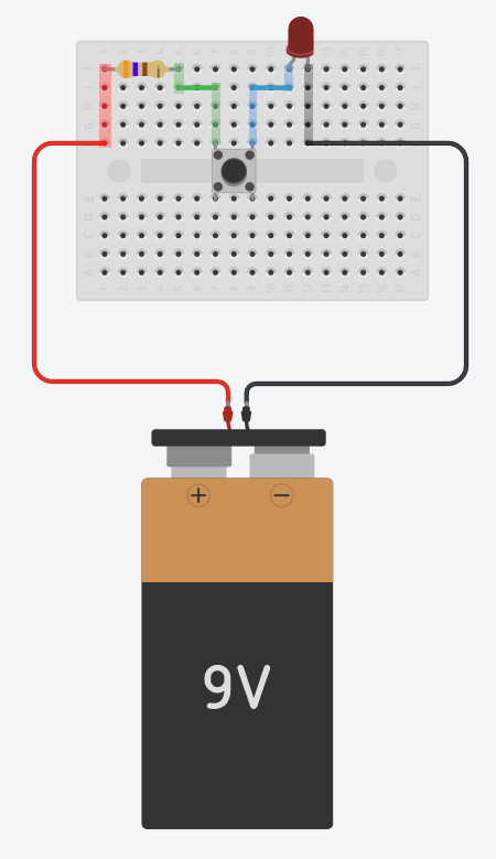
Step 7: Connect the battery
- Connect the red crocodile clip to the plus (+) terminal of the battery.
- Connect the black crocodile clip to the minus (-) terminal of the battery.
Now the battery is ready to give energy to the circuit, but the circuit isn’t closed yet.
If you aren’t sure, call the leader so you can check the circuit together.
Step 8: Test it
- Press the push button.
- Watch the LED.
If the LED lights up while you press the push button, you’ve done it!
You have built an electronic circuit on a breadboard without soldering.
If the LED doesn’t light up
That’s normal. Electronics engineers often have to find a small mistake in the wiring.
Don’t swap all the parts at once. Check one thing at a time.
Checklist:
- Is the battery connected correctly?
- Is the red wire in the group of holes with the left leg of the resistor?
- Is the black wire in the group of holes with the shorter leg of the LED?
- Is the LED the right way round?
- Does the LED have a resistor?
- Are the legs of the LED in different groups of holes?
- Is the push button across the middle gap?
- Are the wires pushed in properly?
- Is there a short circuit anywhere between plus and minus?
Finding and fixing a mistake is called debugging.
Important!
If the battery, a wire, the LED or the resistor starts to get hot, switch off the battery holder straight away and call the leader.Safety rules
Today we are using batteries and low-voltage components, but good rules always apply:
- Switch off the power before changing wires.
- Never connect plus and minus directly with just a wire.
- Always use a resistor with an LED.
- Don’t force parts into the breadboard.
- Don’t work with wet hands.
- Don’t keep water, juice or food next to the electronics.
- Don’t touch wall sockets, chargers or devices plugged into the wall.
- If something gets hot, smells strange or doesn’t work as it should, call the leader straight away.
- At the end of the workshop, switch off the power and put the parts back in their box.
Extra challenges
If your basic circuit works, try one or more of these challenges:
- Swap the LED for one of a different colour.
- Add a second LED with its own resistor.
- Try to explain to a friend why an LED has a longer and a shorter leg.
- Move the push button to a different place in the circuit. Does the LED still work?
- Make a secret signal by pressing the push button in a rhythm you have agreed on.
- Draw your circuit and label the battery, plus, minus, resistor, LED, push button and wires.
- Make a cardboard case for your LED light.
- Invent a device that could be switched on by pressing a push button.
Link to the micro:bit
Today we switched the LED on by hand with a push button.
Later on, the micro:bit can become the programmable controller of our circuit.
The micro:bit can:
- Tell when we press a push button.
- Read data from a sensor.
- Switch on an external LED.
- Play a sound on a buzzer.
- Control a motor or another part of the project.
Later on we can connect the micro:bit to the breadboard with crocodile clips and use its pins to control external LEDs and other components. In circuits like these, the LED still needs a resistor to limit the current.
 What did we learn?
- A breadboard is used to build electronic circuits quickly without soldering.
- There are hidden metal connections under the holes of a breadboard.
- Not all the holes on a breadboard are connected to each other.
- The plus and minus lines bring energy to different parts of the circuit.
- An LED has a direction and needs a resistor.
- A push button can open and close a circuit.
- We build and test a circuit step by step.
- Debugging means finding and fixing a mistake.
- We always switch off the power before changing wires.
Questions to finish
1. What is a breadboard and why do we use it?
2. Are all the holes on a breadboard connected to each other?
3. What are the plus and minus lines along the edge of the breadboard for?
4. Why does an LED have a longer and a shorter leg?
5. Why do we always use a resistor with an LED?
6. What happens to the circuit when we press the push button?
7. Why do we often place the push button across the middle gap of the breadboard?
8. Name two things you would check if the LED doesn't light up.
9. What does the word debugging mean?
10. How could the micro:bit replace the push button in our project?
11. What is the value of the resistor and why that value?
For our LED we use a 360 Ω resistor (360 ohms).
A 360 Ω resistor reduces the electric current enough for the LED to light up safely, while it still stays bright enough for us to see it well in the classroom.
We don’t connect the LED straight to the battery. Without a resistor, too much current could flow through the LED. Then the LED could get very hot, stop working or be damaged.
We choose the resistor value based on three things:
- the voltage of the battery or other power source,
- the colour and type of the LED,
- how much current the LED is allowed to take.
For a red LED in a simple battery circuit of about 9 V, a 360 Ω resistor is a practical and safe value for the workshop. Resistors from 360 Ω to 1 kΩ can also be a good choice: with a bigger resistor the LED glows more dimly, but it is still well protected. We don’t use a resistor smaller than 360 Ω, because too much current would flow through the LED.
We recognise resistors by their coloured bands. On a 360 Ω resistor the colours are:
- orange = 3
- blue = 6
- brown = ×10
or
- orange = 3
- blue = 6
- black = 0
- black = ×1
A gold or silver band shows that the real value of the resistor may be slightly different from the value written on it, but it is still close enough for our project.