
Traffic lights for cars and pedestrians
The Arduino controls a traffic light for cars, a pedestrian light and a sound signal, and our own function keeps the program short and easy to read
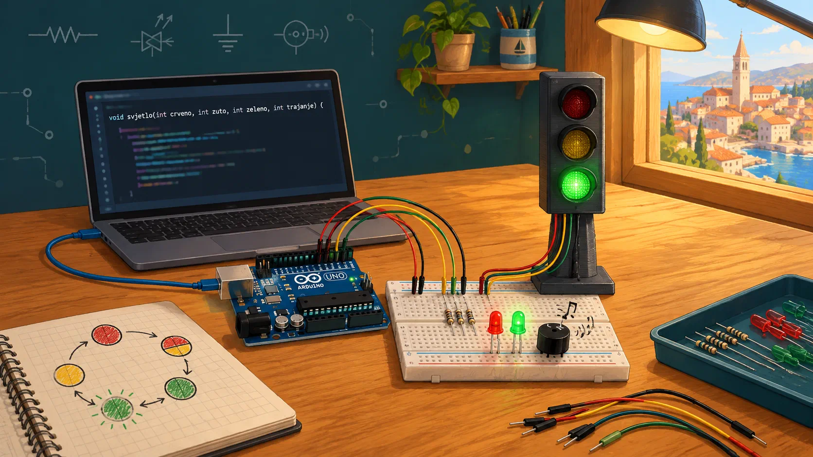
A traffic light at a crossroads looks simple: three lights that switch on one after another. But behind it is a program that must know exactly which light may be on, for how long, and whether pedestrians may start walking at that moment.
Today we will build such a traffic light step by step. First we will use the Arduino to control a 3D-printed traffic light for cars. Then we will add a pedestrian light, and finally a sound signal that helps people with poor sight.
The most important programming technique in today’s workshop is our own function. We will see how one well-designed function lets us give the traffic light completely new behaviour without changing the main part of the program at all.
How does our traffic light work?
The traffic light goes through states. A state is one combination of lights that are on, and it lasts for some time.
| Step | Cars | Pedestrians | Duration |
|---|---|---|---|
| 1 | red | wait | 4 s |
| 2 | red + yellow | wait | 1 s |
| 3 | green | walk | 4 s |
| 4 | green blinks | wait | 2 s |
| 5 | yellow | wait | 1 s |
| ⇒ | back to step 1 |
Imagine a crossroads. Our cars drive straight through the crossroads, and our pedestrians walk along the pavement next to them, in the same direction, and cross the side street on a zebra crossing. So cars and pedestrians move side by side, and their paths never cross. That is why pedestrians may start walking when the cars have green. When the green starts to blink, pedestrians no longer start walking.
Pedestrians do not cross the road in front of our cars. For them the opposite rule would apply: they may start walking only when the cars have red.
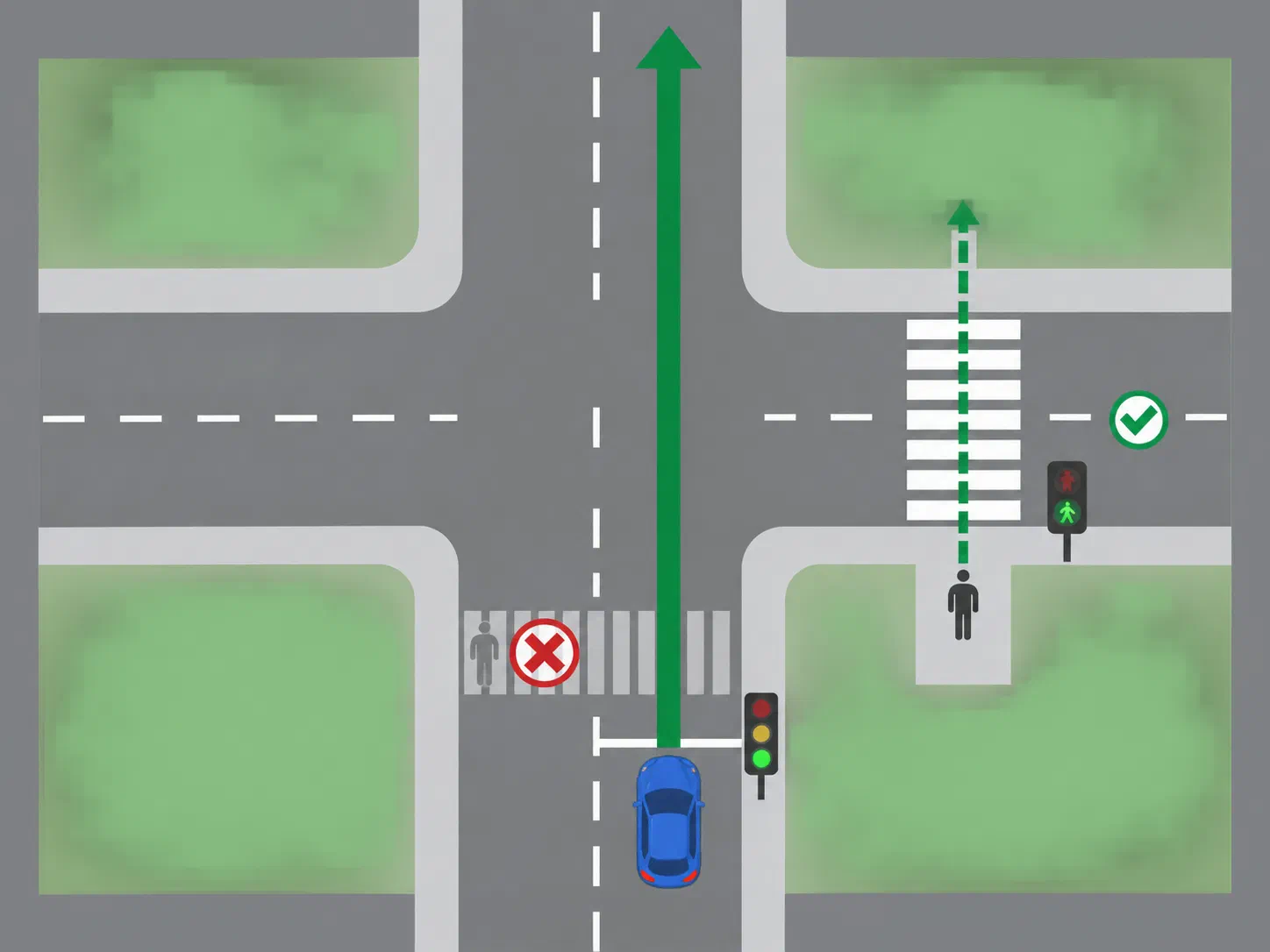
The most important rules of our traffic light:
- red and green for cars are never on at the same time;
- pedestrians walk only when the cars have steady green.
In one of the next workshops we will build a real crossroads from traffic lights like this one. Each Arduino will control the traffic light for cars and the pedestrian light for one direction, exactly as today.
Pedestrians and turning cars
At real crossroads, a car that is turning may drive across a zebra crossing where pedestrians have green at that very moment. The driver must then let the pedestrians cross first. That is why real traffic lights often have extra lights and more complicated rules. Our model is simpler, so that we can understand the basic logic first.
Materials
Each person gets:
- an Arduino Uno and a USB cable
- a large breadboard
- a 3D-printed traffic light with four wires: red, yellow, green and black
- a red and a green LED for the pedestrians
- 5 × 220 Ω resistors (red-red-brown)
- an active buzzer and a 68 Ω resistor (blue-grey-black)
- jumper wires
Wiring rules
- While we are wiring, the Arduino is unplugged from the USB cable.
- We don’t connect 5 V to the breadboard. The LEDs and the buzzer are powered by the Arduino’s pins, so from the Arduino we only need GND. If there is no 5 V on the board, there can’t be a short circuit between 5 V and GND either.
- We connect the Arduino’s GND to the (–) rail. Everything that goes to GND goes into that rail.
- On many large breadboards the rails are split in the middle of the board (you can see a gap in the coloured line). That is why we connect everything in the top half of the board, in rows 1 to 30 (or we bridge the gaps with short wires).
- Every LED has its own resistor.
- Before we plug in the USB cable, the workshop leader checks the circuit.
If you need a reminder of how the holes on the board are connected, look at Breadboard.
Exercise 1: The traffic light for cars
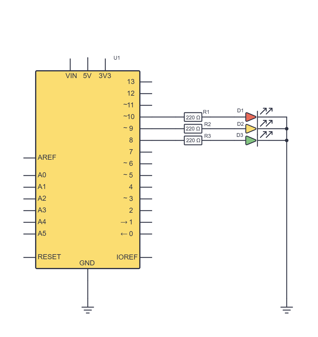
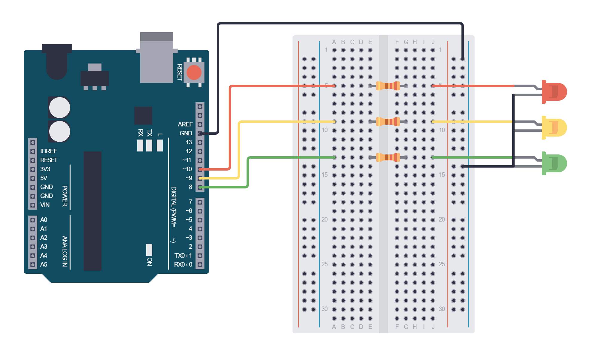
Wiring
We place each resistor across the centre gap of the board, in a single row. The wire from the Arduino goes into the left half of the row (columns a–e), and the traffic light’s wire into the right half (columns f–j). The resistor connects the left and right halves of the row.
| Light | Arduino pin | Wire from the Arduino | 220 Ω resistor | Right side |
|---|---|---|---|---|
| Red | D10 | a5 | e5–f5 | red wire of the traffic light in j5 |
| Yellow | D9 | a9 | e9–f9 | yellow wire of the traffic light in j9 |
| Green | D8 | a13 | e13–f13 | green wire of the traffic light in j13 |
| Common GND | GND | right – rail | – | black wire of the traffic light in the – rail |
How much current flows through the LED? About 2 V stays across the red LED, so approximately 5 V – 2 V = 3 V is left across the resistor. By Ohm’s law from lesson 1.2 (I = U / R), about 3 V / 220 Ω = 14 mA flows through the resistor and the LED. That is below the recommended 20 mA per Arduino pin.
Why D10, D9 and D8? The Arduino uses pins D0 and D1 to communicate with the computer over USB, and we leave D3 and D11 free because the command we will use for sound affects them.
After wiring, check:
- the traffic light’s black wire is in the – rail, and the Arduino’s GND is in the same rail;
- every colour has its own resistor;
- no wire is connected to 5 V;
- the workshop leader has checked the circuit.
Colour test
The first program switches the lights on one at a time, so that we can check that each colour is on the right pin.
// C++
const int carRed = 10;
const int carYellow = 9;
const int carGreen = 8;

void setup() {
  pinMode(carRed, OUTPUT);
  pinMode(carYellow, OUTPUT);
  pinMode(carGreen, OUTPUT);
}

void loop() {
  digitalWrite(carRed, HIGH);
  delay(1000);
  digitalWrite(carRed, LOW);

  digitalWrite(carYellow, HIGH);
  delay(1000);
  digitalWrite(carYellow, LOW);

  digitalWrite(carGreen, HIGH);
  delay(1000);
  digitalWrite(carGreen, LOW);
}
The lights must switch on in order: red, yellow, green. If the order is different, we don’t change the program; we check the wires.
Variable names may only contain English letters, digits and the underscore _, and no spaces. That is why we write carYellow and not car yellow.
What is new in the program?
digitalWrite(carRed, HIGH);– Switches the pin on: it is at about 5 V and the LED lights up.digitalWrite(carRed, LOW);– Switches the pin off: it is at 0 V and the LED is off.- In the last lesson
analogWrite()had 256 levels, from 0 to 255.digitalWrite()knows only two:HIGHorLOW. That is enough for a traffic light, because a light is either on or off.
What happens if we swap the traffic light's red and yellow wires by mistake?
Exercise 2: The whole cycle
Now we want the traffic light to go through all the states from the state table.
In every state we must set all three lights, because we don’t want a light from the previous state to stay on. Just the first two states would look like this:
// C++
digitalWrite(carRed, HIGH);      // red
digitalWrite(carYellow, LOW);
digitalWrite(carGreen, LOW);
delay(4000);

digitalWrite(carRed, HIGH);      // red + yellow
digitalWrite(carYellow, HIGH);
digitalWrite(carGreen, LOW);
delay(1000);
For the whole cycle, with blinking, we would need about thirty almost identical lines. It is easy to write HIGH instead of LOW somewhere, and a mistake like that is hard to find. So we will write our own function: a new command that sets all three lights at once.
Why do we write our own functions?
A function is a group of commands that we give a name. Once we have written it, we call it by its name, as if it were a new command of the C++ language. We already use functions: digitalWrite(), delay() and analogRead() were written by other programmers, and we just call them. If you came to the micro:bit workshop, we built the same idea from blocks there, in the function Svjetlo (Croatian for "light").
What do we gain with our own function lights() for our traffic light?
- A shorter program. We write the three commands for the three lights only once, not in every state.
- A readable program. The call
lights(HIGH, HIGH, LOW)reads like one row of the state table: red yes, yellow yes, green no. - Fewer mistakes. Every call sets all three lights, so we can't forget to switch one of them off.
- One place for changes. If we want to change how the lights are switched, we change only the function, and the cycle in
loop()stays the same. That is exactly what we will use today when we add pedestrians and sound to the traffic light.
Programmers say that a function hides how something is done, and the rest of the program only says what we want.
// C++
const int carRed = 10;
const int carYellow = 9;
const int carGreen = 8;

void lights(int red, int yellow, int green) {
  digitalWrite(carRed, red);
  digitalWrite(carYellow, yellow);
  digitalWrite(carGreen, green);
}

void setup() {
  pinMode(carRed, OUTPUT);
  pinMode(carYellow, OUTPUT);
  pinMode(carGreen, OUTPUT);
}

void loop() {
  lights(HIGH, LOW, LOW);      // red
  delay(4000);
  lights(HIGH, HIGH, LOW);     // red + yellow
  delay(1000);
  lights(LOW, LOW, HIGH);      // green
  delay(4000);

  for (int i = 0; i < 4; i++) {  // green blinks 4 times
    lights(LOW, LOW, LOW);
    delay(250);
    lights(LOW, LOW, HIGH);
    delay(250);
  }

  lights(LOW, HIGH, LOW);      // yellow
  delay(1000);
}
What is new in the program?
void lights(int red, int yellow, int green) { ... }– This is how we create our own function.lightsis its name, and between the curly brackets{ }are the commands it carries out. We write the function abovesetup(), as in the last lesson.void– Means that the function just does something and doesn’t return a result.int red, int yellow, int green– These are parameters: empty slots that we fill in when we call the function. Inside the function we use them like ordinary variables.lights(HIGH, HIGH, LOW);– A call of the function. The values are handed over in order: the first goes intored, the second intoyellow, the third intogreen.for (int i = 0; i < 4; i++) { ... }– The loop repeats the commands between{ }a set number of times. The brackets hold three parts: where we start (i = 0), how long we repeat (i < 4) and the step (i++increasesiby one, the opposite of thecount--command from the last lesson). The counter goes 0, 1, 2, 3, so four times.
How long does one whole cycle of the traffic light last?
Exercise 3: Playing with parameters
Function parameters don’t have to be just HIGH and LOW. We will add two more things to the function:
duration– a fourth parameter that says how long the state lasts. The waiting moves into the function, andloop()no longer needsdelay().BLINK– to the Arduino,HIGHis really the number 1, andLOWthe number 0. We will invent a third value, the number 2, which means blink. When the function gets it, it will do the blinking by itself.
The pin constants and setup() stay the same. Below the constants add BLINK, and replace the lights() function and loop() with these:
// C++
const int BLINK = 2;   // a third value next to LOW (0) and HIGH (1)

void lights(int red, int yellow, int green, int duration) {
  digitalWrite(carRed, red);
  digitalWrite(carYellow, yellow);

  if (green == BLINK) {
    for (int t = 0; t < duration; t = t + 500) {
      digitalWrite(carGreen, LOW);
      delay(250);
      digitalWrite(carGreen, HIGH);
      delay(250);
    }
  } else {
    digitalWrite(carGreen, green);
    delay(duration);
  }
}

void loop() {
  lights(HIGH, LOW, LOW, 4000);     // red
  lights(HIGH, HIGH, LOW, 1000);    // red + yellow
  lights(LOW, LOW, HIGH, 4000);     // green
  lights(LOW, LOW, BLINK, 2000);    // green blinks
  lights(LOW, HIGH, LOW, 1000);     // yellow
}
What is new in the program?
int duration– The fourth parameter: how many milliseconds the state lasts.const int BLINK = 2;– A name for the number 2. We write it in capital letters because it is the same kind of thing asHIGHandLOW: a name for a number with a special meaning.if (green == BLINK) { ... } else { ... }– If green should blink, the function switches it on and off. Otherwise (else) it just sets green and waits. Only one of the two parts ever runs.for (int t = 0; t < duration; t = t + 500)– The same loop as before, but with a different step. One round takes 250 + 250 = 500 ms, sotcounts how much time has passed.loop()is now five lines long and looks almost like the state table: one state, one line.
Experiments
For each experiment we change only loop(). We don’t touch the function.
1. A fast and a slow traffic light
Change the duration numbers. Try to make a traffic light whose whole cycle lasts 6 s, and then one whose cycle lasts 20 s.
2. Night mode
At night, the traffic lights at some crossroads only blink yellow. Replace the whole loop() with this:
// C++
void loop() {
  lights(LOW, HIGH, LOW, 500);   // yellow
  lights(LOW, LOW, LOW, 500);    // everything off
}
We got completely new behaviour just from different parameters.
3. The broken traffic light
Type the line lights(HIGH, LOW, HIGH, 3000); into loop(). The program runs it without complaint: red and green are on together.
Why is the broken traffic light dangerous, and who should prevent a mistake like this?
How many times does green blink if we write lights(LOW, LOW, BLINK, 1700)?
t takes the values 0, 500, 1000 and 1500, and the next value, 2000, is no longer less than 1700. So the blinking really lasts 2000 ms, not 1700 ms.Before the next exercise, put back the loop() with the five states.
Exercise 4: The pedestrian light
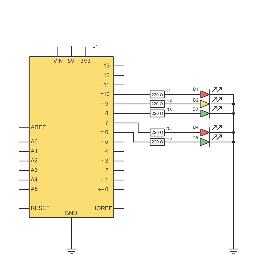
Wiring
We add two LEDs to the breadboard, each with its own 220 Ω resistor. We connect them in the same way as the lights of the traffic light, but now the LED sits directly on the board:
| Light | Arduino pin | Wire from the Arduino | 220 Ω resistor | Right side |
|---|---|---|---|---|
| Pedestrians red | D7 | a18 | e18–f18 | red LED: longer leg in j18, shorter leg in the right – rail |
| Pedestrians green | D6 | a22 | e22–f22 | green LED: longer leg in j22, shorter leg in the right – rail |
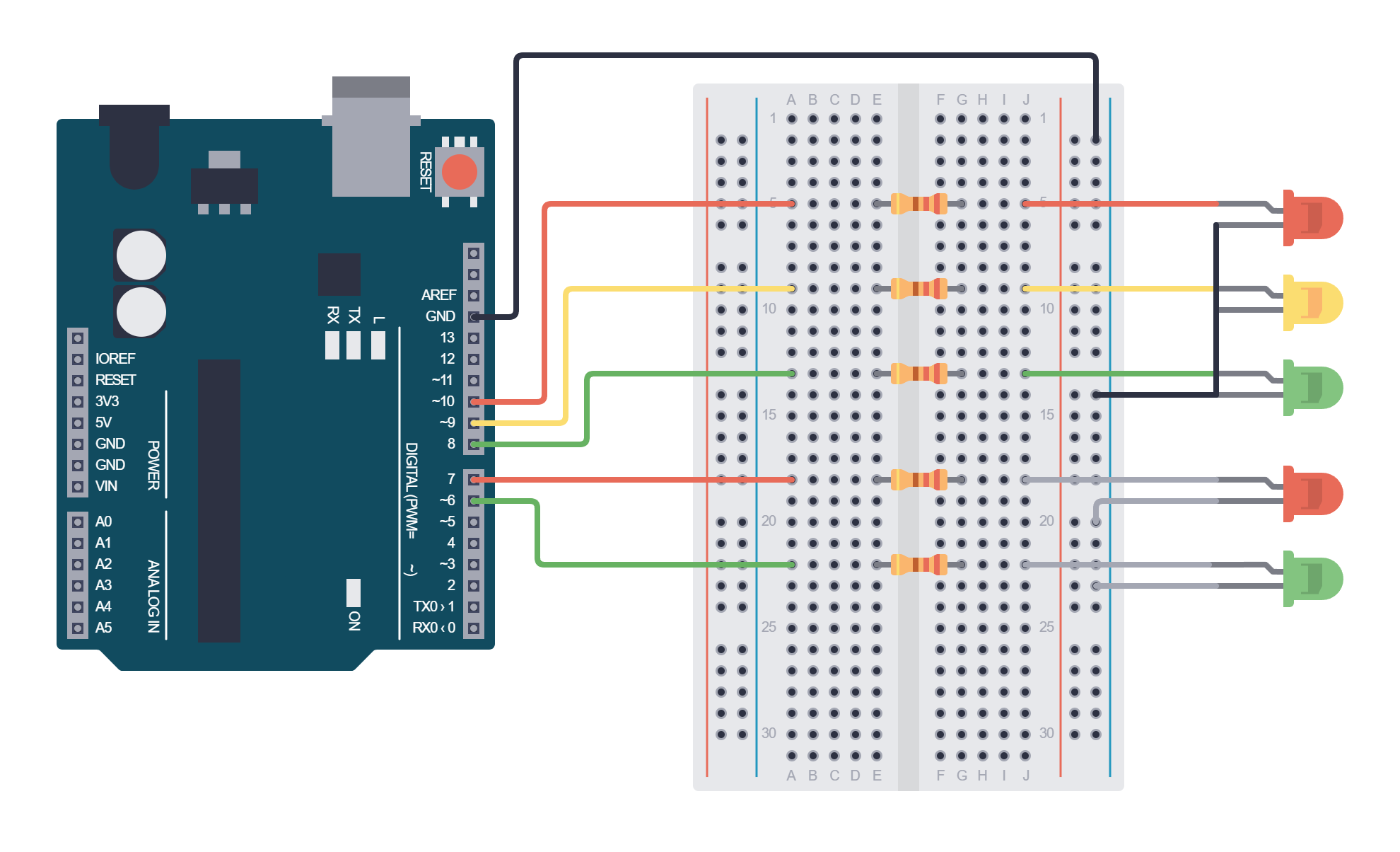
In the traffic light for cars, the polarity of the LEDs is sorted out inside the model. Here we have to take care of it ourselves:
- the longer leg (anode) goes towards the resistor and the pin;
- the shorter leg (cathode), on the side where the edge of the LED’s body is flat, goes towards GND.
An LED that is the wrong way round won’t light up, but it won’t be damaged either. If it doesn’t light up, turn it round.
Now at most three LEDs are on at the same time, for example red and yellow for cars and red for pedestrians. That is about 40 mA in total, which the Arduino Uno supplies without any trouble.
The rule for pedestrians
Where in the program should we write this rule? In loop() we would have to add the pedestrians to every state. But there is a better place: the lights() function. It is the only part of the program that always knows which lights the cars are getting right now.
Changing the program
Below the constants for cars add:
// C++
const int pedestrianRed = 7;
const int pedestrianGreen = 6;
In setup() add:
// C++
  pinMode(pedestrianRed, OUTPUT);
  pinMode(pedestrianGreen, OUTPUT);
In the lights() function add the block marked NEW, after setting red and yellow, and before the part that waits:
// C++
void lights(int red, int yellow, int green, int duration) {
  digitalWrite(carRed, red);
  digitalWrite(carYellow, yellow);

  // NEW: pedestrians walk only when the cars have steady green.
  if (green == HIGH && red == LOW && yellow == LOW) {
    digitalWrite(pedestrianRed, LOW);
    digitalWrite(pedestrianGreen, HIGH);
  } else {
    digitalWrite(pedestrianRed, HIGH);
    digitalWrite(pedestrianGreen, LOW);
  }

  if (green == BLINK) {
    for (int t = 0; t < duration; t = t + 500) {
      digitalWrite(carGreen, LOW);
      delay(250);
      digitalWrite(carGreen, HIGH);
      delay(250);
    }
  } else {
    digitalWrite(carGreen, green);
    delay(duration);
  }
}
We didn’t change a single character in loop(). The traffic light got a completely new job, and the cycle stayed the same. That is what our own function gave us.
What is new in the program?
&&– Means and. The condition is true only if all parts are true: green is on and red is off and yellow is off.else– In all other states the pedestrians get red. We don’t have to list every state separately.- Why do pedestrians wait while green blinks? Then the parameter
greenis equal toBLINK(2), notHIGH(1), so the condition isn’t true. The value we invented for blinking now tells steady green and blinking green apart for free. - Why do we also check red and yellow? Because of the broken traffic light from Exercise 3. If someone calls
lights(HIGH, LOW, HIGH, 3000), the pedestrians still stay on red. The function protects the pedestrians even from a wrong call. - Why does the block go before the waiting? While
delay()is running, the Arduino does nothing else. All decisions must be made before we start waiting.
What do the pedestrians see when the traffic light runs in night mode from Exercise 3?
Exercise 5: A sound signal for pedestrians
A person with poor sight can’t see the pedestrian light. That is why many traffic lights also give a sound signal. Ours will be short and quiet:
- when the pedestrians get green: a short higher sound, go;
- when the pedestrians lose green: a short lower sound, stop;
- the rest of the time: silence.
The active buzzer
An active buzzer has a small electronic circuit inside that produces a tone. When it gets a voltage, it buzzes by itself, always with the same tone. We can’t change the pitch of that tone.
But we can switch it on and off very quickly. Then we hear a new sound: when we switch it on and off faster, the sound is higher, and when we do it more slowly, the sound is deeper and rougher. These aren’t pure tones like those of a musical instrument, but they are clearly different.
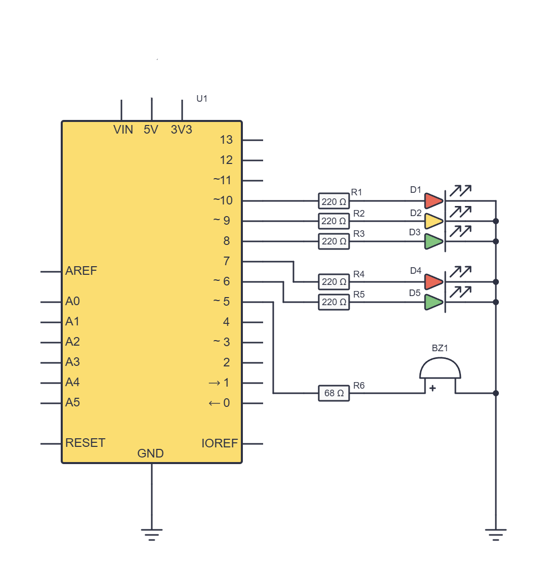
Wiring
| Part | Arduino pin | Wire from the Arduino | 68 Ω resistor | Right side |
|---|---|---|---|---|
| Buzzer | D5 | a27 | e27–f27 | + leg of the buzzer in j27, the other leg in the – rail |
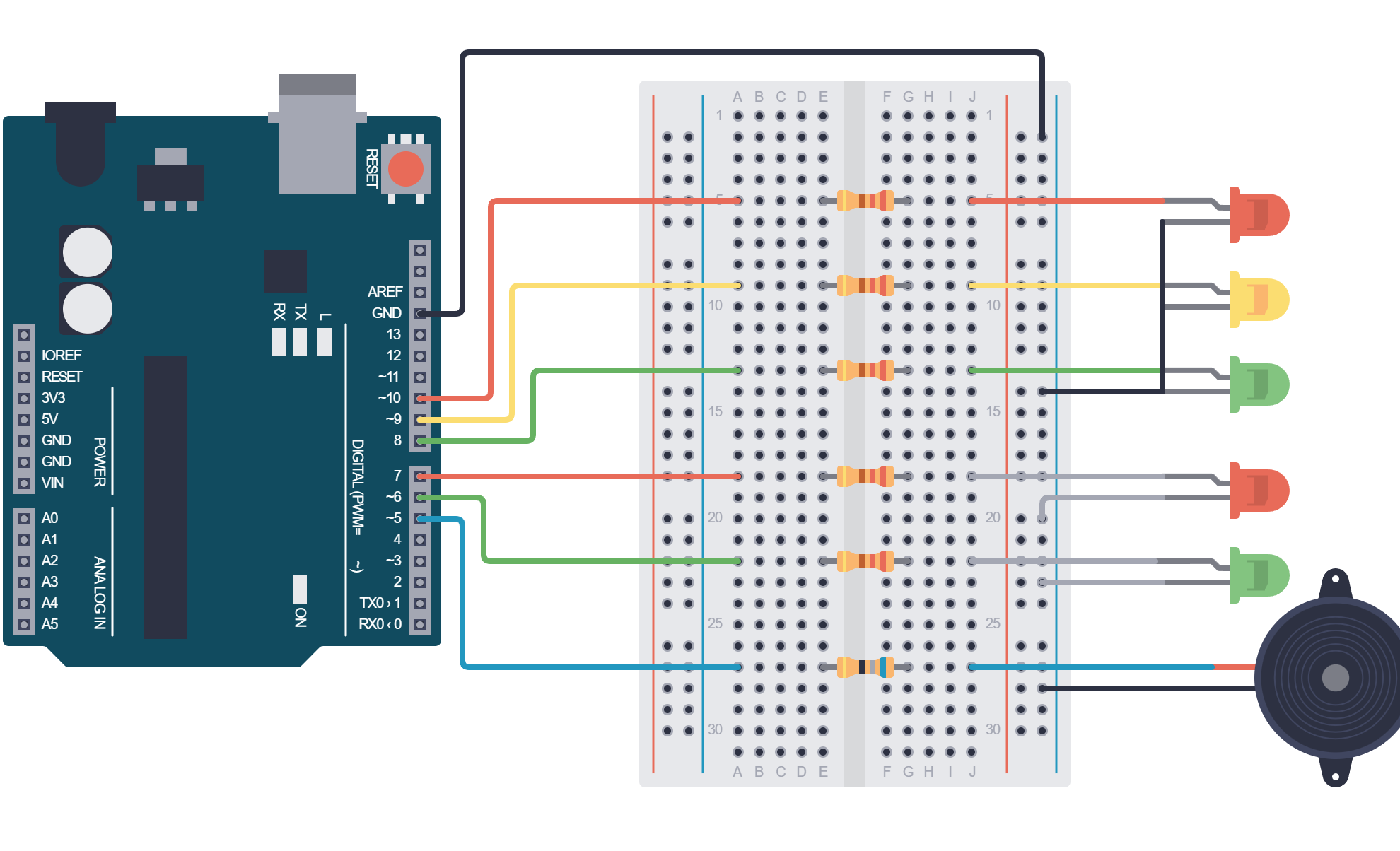
- The buzzer has polarity. The + leg is longer, and there is also a + mark on the top of the case. A buzzer that is the wrong way round stays silent.
- The 68 Ω resistor reduces the current through the pin and also makes the buzzer quieter.
The rule for sound
Why do we have to remember what the pedestrians were doing? The lights() function is called five times in every cycle, and in four of those calls the pedestrians have red. Without remembering, the lower sound would buzz four times in each cycle. We want a sound only when the pedestrians’ state changes.
Changing the program
Below the other constants add:
// C++
const int buzzer = 5;

bool pedestriansWalking = false;    // remembers whether the pedestrians had green
In setup() add pinMode(buzzer, OUTPUT);, and in the lights() function extend the pedestrian block like this:
// C++
  // Pedestrians walk only when the cars have steady green.
  if (green == HIGH && red == LOW && yellow == LOW) {
    digitalWrite(pedestrianRed, LOW);
    digitalWrite(pedestrianGreen, HIGH);
    if (!pedestriansWalking) {     // they have just got green
      tone(buzzer, 800, 60);       // short higher sound: go
      pedestriansWalking = true;
    }
  } else {
    digitalWrite(pedestrianRed, HIGH);
    digitalWrite(pedestrianGreen, LOW);
    if (pedestriansWalking) {      // they have just got red
      tone(buzzer, 150, 150);      // short lower sound: stop
      pedestriansWalking = false;
    }
  }
Here too, loop() stays the same.
What is new in the program?
tone(buzzer, 800, 60);– For 60 milliseconds it switches the buzzer on and off 800 times a second. We hear a short, higher sound.tone(buzzer, 150, 150);– For 150 milliseconds it switches the buzzer on and off only 150 times a second. We hear a slightly longer, deeper and rougher sound.tone()plays in the background: the program doesn’t wait for the sound to finish, but carries on straight away. So the lights don’t get stuck because of the sound.bool pedestriansWalking = false;– A logical (true/false) variable that remembers the pedestrians’ previous state, likeledModein the last lesson. At the start the pedestrians are waiting, so the value isfalse.if (!pedestriansWalking)– The!sign means not: “if the pedestrians weren’t walking until now”.- The sounds differ both in pitch and in length. The short one means go, and the slightly longer one stop. That way they are also easier to recognise for someone who finds it hard to tell pitches apart.
Mind the noise
Active buzzers are loud, and there are many of them working in the room at the same time. That is why our traffic light makes a sound only twice in a 12-second cycle, and each sound lasts less than a fifth of a second.
- If the buzzer is still too loud, stick a small piece of sticky tape over its opening.
- While you are experimenting with durations or with the program, pull the buzzer's wire out of pin D5.
What do real traffic lights sound like?
Real sound signals for people with poor sight usually tick all the time: slowly while the pedestrians have red, and quickly while they have green. The slow ticking helps a person find the traffic light pole, and the fast ticking tells them they may cross the road. Our traffic light uses a quieter version with two short sounds.
Why do we hear the lower sound exactly when the green for cars starts to blink?
green equal to BLINK, so the condition for pedestrians isn’t true and the program goes into the else part. In the previous state the pedestrians were walking, so pedestriansWalking is still true: the program plays the lower sound and remembers that the pedestrians are now waiting. In the following states pedestriansWalking is false, so there is no more sound.The whole program
// C++
const int carRed = 10;
const int carYellow = 9;
const int carGreen = 8;
const int pedestrianRed = 7;
const int pedestrianGreen = 6;
const int buzzer = 5;

const int BLINK = 2;                // a third value next to LOW (0) and HIGH (1)

bool pedestriansWalking = false;    // remembers whether the pedestrians had green

void lights(int red, int yellow, int green, int duration) {
  digitalWrite(carRed, red);
  digitalWrite(carYellow, yellow);

  // Pedestrians walk only when the cars have steady green.
  if (green == HIGH && red == LOW && yellow == LOW) {
    digitalWrite(pedestrianRed, LOW);
    digitalWrite(pedestrianGreen, HIGH);
    if (!pedestriansWalking) {     // they have just got green
      tone(buzzer, 800, 60);       // short higher sound: go
      pedestriansWalking = true;
    }
  } else {
    digitalWrite(pedestrianRed, HIGH);
    digitalWrite(pedestrianGreen, LOW);
    if (pedestriansWalking) {      // they have just got red
      tone(buzzer, 150, 150);      // short lower sound: stop
      pedestriansWalking = false;
    }
  }

  if (green == BLINK) {
    for (int t = 0; t < duration; t = t + 500) {
      digitalWrite(carGreen, LOW);
      delay(250);
      digitalWrite(carGreen, HIGH);
      delay(250);
    }
  } else {
    digitalWrite(carGreen, green);
    delay(duration);
  }
}

void setup() {
  pinMode(carRed, OUTPUT);
  pinMode(carYellow, OUTPUT);
  pinMode(carGreen, OUTPUT);
  pinMode(pedestrianRed, OUTPUT);
  pinMode(pedestrianGreen, OUTPUT);
  pinMode(buzzer, OUTPUT);
}

void loop() {
  lights(HIGH, LOW, LOW, 4000);     // red
  lights(HIGH, HIGH, LOW, 1000);    // red + yellow
  lights(LOW, LOW, HIGH, 4000);     // green
  lights(LOW, LOW, BLINK, 2000);    // green blinks
  lights(LOW, HIGH, LOW, 1000);     // yellow
}
If something doesn’t work
- No light comes on ⇒ Is the Arduino’s GND connected to the same – rail as the traffic light’s black wire? Is the rail split in the middle of the board?
- The lights come on in the wrong order ⇒ The traffic light’s wires are in the wrong rows. Compare the circuit with the table in Exercise 1.
- One pedestrian LED doesn’t light up ⇒ It is probably the wrong way round. The longer leg goes towards the resistor.
- The buzzer is silent ⇒ Check the buzzer’s polarity and whether the wire is in pin D5.
- The buzzer buzzes all the time and goes quiet when it should buzz ⇒ Some buzzer modules work the other way round: they buzz when the pin is
LOW. Ask the workshop leader. - The program won’t upload ⇒ Check that the Arduino Uno board and the right port are selected in the Arduino IDE.
Extra challenges
- Instead of one higher sound for go, play two, with
delay(150);between them. Do you notice that the green for cars now comes on a little later? Why? What could you change in the program so that all the lights aren’t off for that short time? - Change the durations so that the green for cars, together with the blinking, lasts exactly half of the whole cycle.
 What did we learn?
digitalWrite()sets a digital pin toHIGH(about 5 V) orLOW(0 V).- Every LED needs its own resistor. With 220 Ω and 5 V, about 14 mA flows through the LED.
- We don’t connect 5 V to the breadboard when we don’t need it, and the GND of all parts must be common.
- Our own function is a group of commands with a name. Parameters are empty slots that we fill in when we call it.
- A function makes the program shorter and easier to read, and gives us one place for changes: we added pedestrians and sound without a single change in
loop(). - A
forloop repeats commands a set number of times, or until a set time has passed. if ... elsechooses one of two paths, and&&means and.- We can also give a parameter our own value with a special meaning, such as
BLINK. - A logical variable can remember the previous state, so the program reacts only to a change.
tone()switches the buzzer on and off in the background, which gives the active buzzer a higher or lower sound.
A little quiz
1. What is the difference between digitalWrite() and analogWrite()?
digitalWrite() knows only two states, HIGH and LOW: the pin is on or off. analogWrite() sends a PWM signal with 256 levels (0–255), so an LED can shine more weakly or more brightly.2. What are function parameters?
lights(HIGH, HIGH, LOW, 1000), the parameter red gets HIGH, yellow gets HIGH, green gets LOW, and duration gets 1000. The values are handed over in the order in which the parameters are written.3. Why could we add pedestrians without changing loop()?
lights() function. Every time it is called, it knows which lights the cars are getting, so it can also decide what the pedestrians see. loop() only says what happens (which state and for how long), and the function says how it is shown.4. When is the condition green == HIGH && red == LOW && yellow == LOW true?
green is equal to BLINK, not HIGH, so the condition isn’t true.