
Arduino - step by step
From manual control to an automatic light
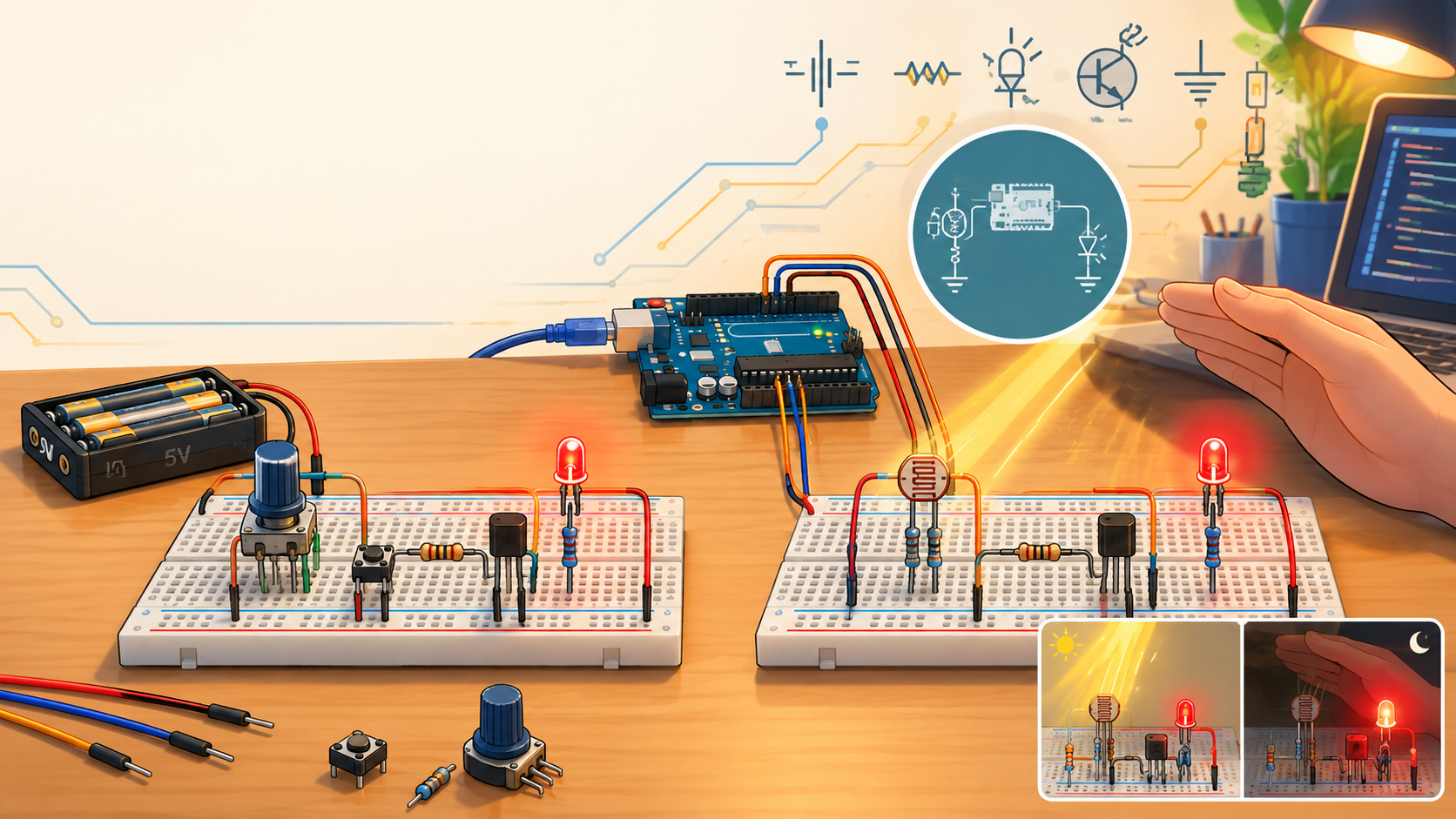
An everyday example: the fridge light
Almost every fridge has a light that switches on automatically when we open the door and switches off when we close it.
In simpler fridges this is done by a switch in the door frame. When the door is closed, it presses the switch and the light goes off. When we open the door, the switch is released and the light comes on.
In this workshop we won’t take apart or wire up a real fridge. Instead, we will build a safe low-voltage model that shows the same principle of controlling a light.
First we will try the same principle with an ordinary push button. The push button will stand in for the fridge door switch.
The classic way to control a light
Let’s first look at this schematic:
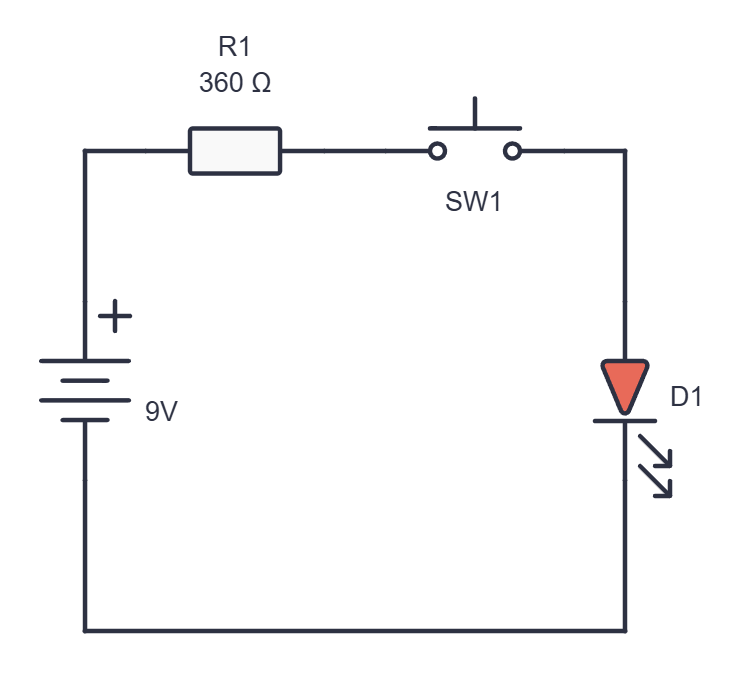
When we press the button, the LED lights up.Can you spot the problem with using this circuit in a fridge?
The goal of this workshop is to understand how a small change in the control part of a circuit can switch on an LED through an NPN transistor.
1. Push button, potentiometer and transistor
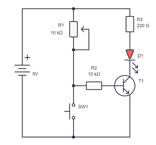
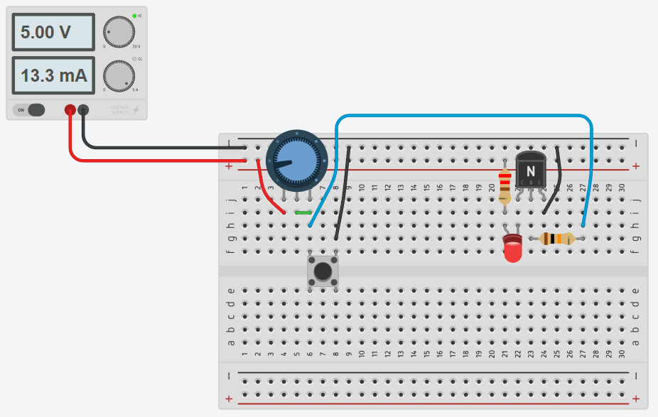
This is the simplest starting circuit. The variable resistor supplies a small control signal (a voltage) to the base of the NPN transistor, which keeps the transistor switched on so that current can flow through the LED. When the push button is pressed, the control voltage disappears (the button connects it to GND, i.e. to 0 V).
Here we use a variable resistor to set the strength of the current through the transistor’s base (the control signal).
We have introduced two new electronic components: the variable resistor and the transistor.
Variable resistor: the potentiometer
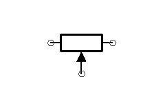
A potentiometer is a resistor whose value we can change by turning its shaft. Inside it has a resistive track and a moving contact called the wiper. That is why it has three terminals: two end terminals and the middle wiper terminal.
Between the two end terminals the resistance is always equal to the potentiometer's rated value, for example 10 kΩ. When we turn the shaft, the resistance between the middle terminal (the wiper) and each end terminal changes.
In this circuit we don't use the potentiometer as a classic voltage divider with three separate connections. We use it as a variable resistor, also called a rheostat. We connect the middle wiper terminal to one of the end terminals, which gives us a resistor with a variable value. So between +5 V and the control point there is always some variable resistance: from roughly 0 Ω to roughly 10 kΩ.
How does an NPN transistor work?
An NPN transistor is an electronic component with three connections: the base (B), the collector (C) and the emitter (E).
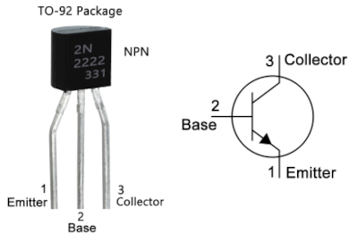
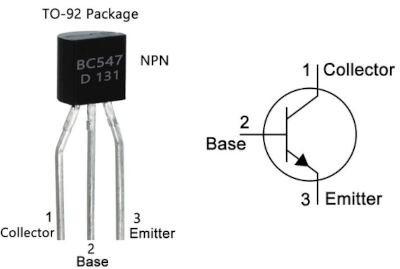
In our circuit the transistor works as an electronic switch. A small change in the voltage and current at the base decides whether a larger current can flow between the collector and the emitter.
- When there isn't enough voltage at the base, the transistor is off. No current flows from the collector to the emitter, so the LED doesn't light up.
- When the base gets enough voltage compared to the emitter, the transistor switches on. Then current can flow through the LED, the collector and the emitter to
GND.
Note that the current we let through the base controls how far the transistor opens, i.e. how much current flows between the collector and the emitter. When a transistor is used as a switch, the base current is large enough to allow the maximum permitted current between the collector and the emitter.
Why do we need R1?
The 10 kΩ variable resistor R1 is called a pull-up resistor.
When the push button isn’t pressed, it pulls the transistor’s base towards +5 V. That way the base isn’t left floating, the transistor stays reliably switched on and the LED stays lit.
Without a pull-up resistor the base can pick up interference or a random voltage. The LED might then glow faintly, flicker or behave unpredictably.
Important: a 1 kΩ protective resistor
If we turn potentiometer R1 all the way, its resistance drops to about 0 Ω. If we then press the push button, +5 V would be connected straight to GND: that is a short circuit.
That is why we connect a 1 kΩ protective resistor (brown – black – red) in series between +5 V and potentiometer R1. It limits the current to about 5 mA at most, whatever the position of the potentiometer. Because 1 kΩ is small compared with the potentiometer's 10 kΩ, the circuit works almost the same.
We keep the same protective resistor in the next two circuits. There it protects the LDR: a brightly lit LDR has a low resistance, so without the protective resistor too much current could flow through it.
Breadboard wiring diagram:
2. Photoresistor (LDR), potentiometer and transistor
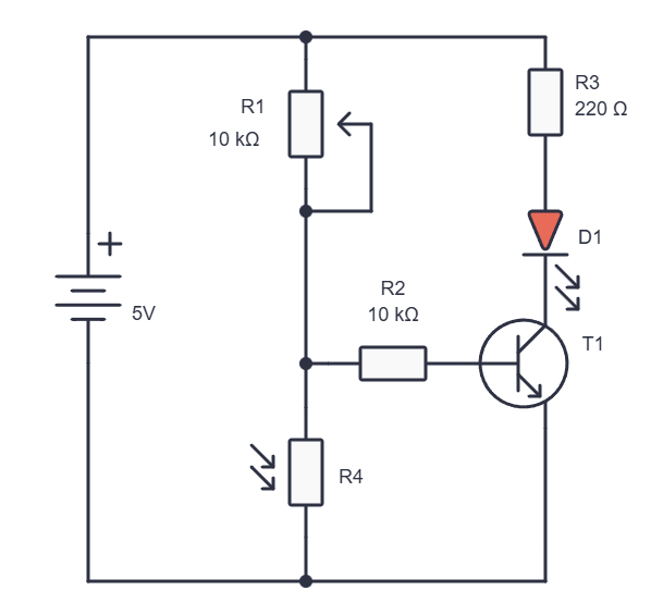
In the second circuit we replace the push button with an LDR, also known as a photoresistor.
An LDR is a resistor whose value changes depending on the amount of light:
- more light ⇒ lower LDR resistance
- less light ⇒ higher LDR resistance
In this circuit the potentiometer R1 and the LDR R4 form a voltage divider.
The voltage at the control point then reaches the transistor’s base through resistor R2.
What is a voltage divider?
A voltage divider (also called a *potential divider*) is a simple circuit with two resistors connected one after the other between the plus of the power supply and ground, i.e. GND.
At the point between the resistors we get a new voltage. This voltage can be lower than the source voltage, and it changes depending on the values of the resistors.
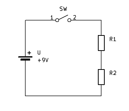
In our circuit the LDR and the 10 kΩ variable resistor together form a voltage divider. When the amount of light changes, the LDR's resistance changes. That is why the voltage at the base of transistor T1 changes too.
How does the circuit react to light?
When the LDR is lit, its resistance is low. It then pulls the control point towards GND more easily, so more current flows through it and less through the transistor’s base, which makes the transistor switch off.
When we cover the LDR and it gets darker, its resistance rises. The potentiometer can then pull the control point towards +5 V.
For this voltage divider:
The potentiometer sets the darkness threshold
The LDR measures how light or dark it is. The potentiometer sets the amount of light at which we want the LED to start switching on.In other words: the LDR is the sensor, and the potentiometer is the manual sensitivity adjustment.
Why is R2 there?
The 10 kΩ resistor R2 sits between the output of the voltage divider and the base of the NPN transistor.
It:
- limits the current that can flow into the transistor’s base
- protects the transistor and the other components
- stops the control part of the circuit from drawing a large current for no reason
- separates the voltage divider from the transistor’s base
Without R2 the transistor’s base could draw too much current, especially when the potentiometer is set to a low resistance and the LDR is in the dark.
3. The Arduino version: the LDR reads the light, the program controls the LED
In the previous circuit the LDR, the variable resistor and the NPN transistor together decided when the LED lights up. Now the Arduino takes over part of the job: it reads the amount of light, its program decides how the LED should react, and then it controls the transistor with a PWM signal.
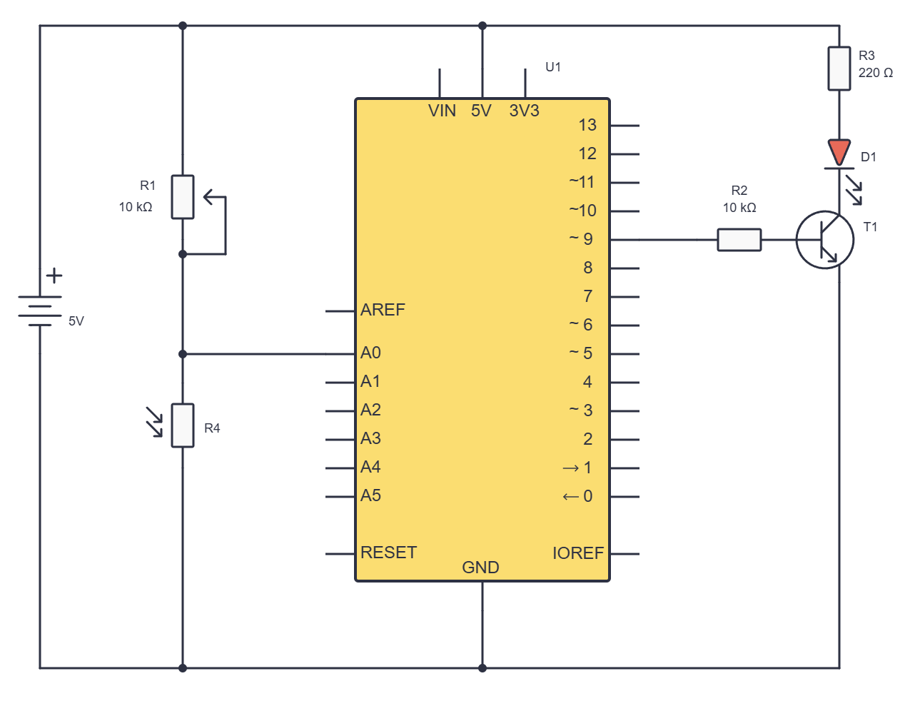
In this version the Arduino doesn’t power the LED directly from its pin. Pin D9 sends a control signal to the base of transistor T1, and the transistor controls the current through the LED. This teaches us an important principle that we will also use later with motors, brighter LEDs, relays and other loads:
The Arduino control principle
The Arduino pin sends a control signal, and the transistor makes it possible to control a separate current path for the load.How is the circuit connected?
The schematic has three main parts:
- LDR and variable resistor ⇒ analogue input
A0 - Arduino PWM output
D9⇒ base resistorR2⇒ base of the NPN transistor +5 V⇒ LED resistorR3⇒ LEDD1⇒ transistor ⇒GND
All parts of the circuit must share a common ground, i.e. GND. This means that the Arduino GND, the minus of the power supply, the bottom end of the LDR and the transistor’s emitter are all connected to the same point.
A common GND is a must
The Arduino can only control the transistor properly if the Arduino and the rest of the circuit share a common ground. IfGND isn't connected, the Arduino D9 signal has no common reference and the LED may behave unpredictably or not react at all.The LDR and analogue input A0
The LDR is a photoresistor. Its resistance changes depending on the amount of light:
- more light ⇒ lower LDR resistance
- less light ⇒ higher LDR resistance
In this schematic the LDR is connected to GND and the potentiometer R1 to +5 V. The potentiometer and the LDR form a voltage divider.
The potentiometer R1 is used as a variable resistor: its middle terminal, the wiper, is connected to one of the end terminals. That is why its resistance between +5 V and point A0 can be changed from roughly 0 Ω to roughly 10 kΩ.
When the LDR is brightly lit, its resistance is lower. It then pulls point A0 towards GND more easily, so the Arduino reads a lower voltage.
When we cover the LDR and it gets darker, its resistance rises. Point A0 is then pulled more towards +5 V through the potentiometer, so the Arduino reads a higher voltage.
- more light ⇒ lower LDR resistance ⇒ lower voltage at
A0⇒ loweranalogRead()value - less light ⇒ higher LDR resistance ⇒ higher voltage at
A0⇒ higheranalogRead()value
The Arduino’s analogue input doesn’t read light directly. It measures the voltage at pin A0 and converts it into a number. On classic Arduino Uno and Nano boards, analogRead() usually returns a value from 0 to 1023.
int lightLevel = analogRead(A0);
D9, PWM and the transistor
Arduino pin D9 is a PWM pin. This means it can switch very quickly between HIGH and LOW.
PWM stands for Pulse Width Modulation. If the pin is on only briefly, the LED looks dimmer. If it is on for most of the time, the LED looks brighter.
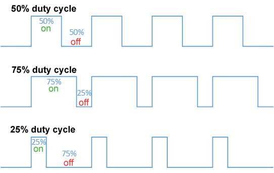
The Arduino program controls PWM with the analogWrite() function:
analogWrite(9, 0);- the LED is offanalogWrite(9, 64);- the LED is dimanalogWrite(9, 128);- the LED is medium brightanalogWrite(9, 255);- the LED is at its brightest
The PWM signal from pinD9doesn’t go straight to the LED. It first passes through the 10 kΩ base resistor R2 and then reaches the base of NPN transistorT1.
Resistor R2 limits the base current. Without it, the Arduino pin and the transistor could be loaded more than necessary.
When Arduino D9 is mostly HIGH, the transistor’s base gets a voltage, the transistor conducts and the LED lights up. When D9 is LOW, the transistor switches off and the LED goes out.
D9 = LOW⇒ transistor off ⇒ LED offD9 = HIGH⇒ transistor conducts ⇒ LED on
When the Arduino sends a PWM signal, the transistor switches on and off very quickly. That is why the LED looks as if its brightness changes gradually.
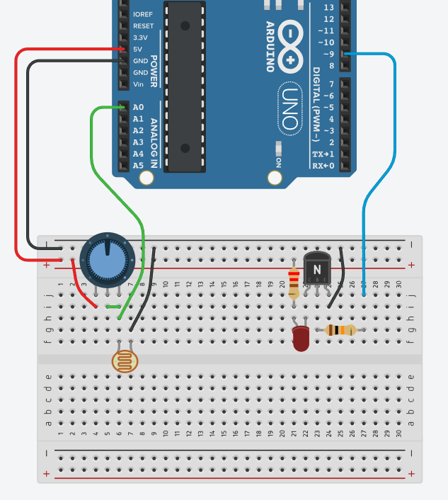
Breadboard wiring diagram:
Program 1: the LED is brighter in the dark
In this schematic a higher value at A0 means more darkness. So we turn a higher sensor value into a higher PWM value for pin D9.
The program works in this order:
analogRead(ldrPin)reads the voltage atA0.- In our circuit, more darkness gives a higher reading.
map()converts the 0–1023 range into the PWM range 0–255.analogWrite()sends the PWM signal to D9.D9controls the transistor’s base throughR2.- The transistor controls the current through the LED.
- The LED shines brighter when the LDR is in the dark.
// C++
const int ldrPin = A0;
const int ledPin = 9;

void setup() {
  pinMode(ledPin, OUTPUT);
  Serial.begin(9600);
}

void loop() {
  int reading = analogRead(ldrPin);  // The darker it is, the higher the reading.

  int ledBrightness = map(reading, 0, 1023, 0, 255);
  ledBrightness = constrain(ledBrightness, 0, 255);

  analogWrite(ledPin, ledBrightness);

  Serial.print("Reading: ");
  Serial.print(reading);
  Serial.print("  PWM LED: ");
  Serial.println(ledBrightness);

  delay(50);
}
Testing and adjusting
After uploading the program, we open the Serial Monitor at 9600 baud.
Then:
- We shine a light at the LDR.
- We cover the LDR with a hand or a piece of cardboard.
- We watch whether the number in the Serial Monitor changes.
- We watch whether the LED reacts by changing its brightness.
- We turn potentiometer
R1and watch how the sensitivity of the circuit changes. - We check whether the LED shines brighter when the LDR is covered.
If the LED shines brighter when the LDR is lit, we first check that the LDR really is connected to GND and the potentiometer to +5 V. If the circuit is wired correctly but we want the opposite behaviour, we can change the order of the numbers in the map() function:
int ledBrightness = map(reading, 0, 1023, 255, 0);
Then a lower value from A0 gives a higher PWM value on D9.
If the circuit doesn’t work
The value in the Serial Monitor doesn’t change
- Possible cause: the LDR or the potentiometer isn’t connected properly
- Check: the connection
+5 V⇒ 1 kΩ protective resistor ⇒R1⇒A0⇒ LDR ⇒GNDHow to check that the LDR works
The quickest LDR test is a multimeter in Ω mode: in the light the resistance should drop, and in the dark it should rise. If the resistance changes, the LDR is most likely fine.
If the LDR passes the multimeter test but the Arduino always shows 0 or 1023, the problem is most likely not the sensor but the breadboard connection, the resistor in series with the LDR, the wires or the connection to `A0`.
The Arduino always reads 0
- Possible cause:
A0is shorted to GND, or the LDR part isn’t powered - Check: the
A0connection, the LDR andGND
The Arduino always reads 1023
- Possible cause:
A0is permanently at+5 V, or the LDR has no connection toGND - Check: the connections of the potentiometer, the LDR and
A0
The value changes, but the LED doesn’t light up
- Possible cause: the LED is the wrong way round, the wrong transistor or the wrong pinout
- Check: the LED, the C-B-E connections of
T1, the connectionD9⇒R2⇒ base
The LED is always on
- Possible cause: the transistor’s base is always getting a voltage, or the transistor isn’t connected properly
- Check:
R2, the base ofT1, the emitter toGND
The LED only switches on and off, with no visible change in brightness
- Possible cause: the program doesn’t use
analogWrite(), orD9isn’t actually connected - Check: the code, pin
D9, the base resistor
The Arduino resets after connecting
- Possible cause: a short circuit between
+5 VandGND, or a transistor placed the wrong way - Check: unplug the USB, check all the connections, then plug it back in
Program 2: the LED is dimmer in the dark
In reality, when there is more light around, an LED needs to shine brighter to make any difference.
Likewise, if the LED is too bright in the dark, its light can be unpleasant for the human eye.
The schematic stays the same, but we need to rework the program a little.
// C++

const int ldrPin = A0;          // Pin connected to the middle point of the LDR voltage divider.
const int ledPin = 9;           // PWM pin the LED is connected to through a resistor.

const int darkThreshold = 500;  // The threshold at which we consider it to be dark.

const int minBrightness = 20;   // Lowest LED brightness when it is completely dark.
const int maxBrightness = 120;  // Highest LED brightness just after crossing the darkness threshold.

void setup() {
  pinMode(ledPin, OUTPUT);
  Serial.begin(9600);
}

void loop() {
  // Read the analogue voltage from the LDR voltage divider.
  int lightLevel = 1023 - analogRead(ldrPin);
  // The LDR is connected to GND, so a higher reading means more darkness. Subtracting from 1023 gives a value that rises with the light.

  // Variable that stores the LED's PWM value.
  int ledBrightness = 0;

  if (lightLevel < darkThreshold) {
    // The output range in map() is deliberately reversed, from minBrightness to maxBrightness.
    ledBrightness = map(lightLevel, 0, darkThreshold, minBrightness, maxBrightness);

    // Makes sure the PWM value stays within the set range.
    ledBrightness = constrain(ledBrightness, minBrightness, maxBrightness);

    // The LED only switches on when the measured value drops below the darkness threshold.
    ledBrightness = constrain(ledBrightness, 0, 255);
  }
  analogWrite(ledPin, ledBrightness);  // Sends the PWM signal to the LED pin and sets its brightness.

  Serial.print("Light: ");
  Serial.print(lightLevel);
  Serial.print("  PWM LED: ");
  Serial.println(ledBrightness);

  delay(50);
}
How the program works
When the light is greater than or equal to darkThreshold, the LED is off.
As soon as the reading drops below the threshold, the LED switches on. However, in this case the LED isn’t at its brightest in complete darkness:
| Lighting | Example LDR reading | LED |
|---|---|---|
| Bright room | 800 | Off |
| Close to the darkness threshold | 490 | About 117 PWM, fairly visible |
| Darker room | 250 | About 70 PWM |
| Very dark room | 0 | 20 PWM, just a soft glow |
The map() function maps the LDR input range from 0 to darkThreshold onto the PWM range from minBrightness to maxBrightness. On classic Arduino boards analogRead() returns a 10-bit value from 0 to 1023, while analogWrite() for PWM typically uses an 8-bit value from 0 to 255.
What to adjust
You will most likely need to adjust these three constants:
const int darkThreshold = 500;- Find it by watching the values in the Serial Monitor. Measure the value when the room is still bright enough and when you want the LED to start switching on.
const int minBrightness = 20;- A value of about 10 to 30 is usually a good starting point for a soft light in the dark.
const int maxBrightness = 120;- For a small ordinary LED, 80 to 150 is often enough. A value of 255 isn’t necessary, especially in a darkened room.
Pin 9 is suitable for analogWrite() on Arduino Uno, Nano and Mini boards because it is one of the supported PWM pins; on those boards they are pins 3, 5, 6, 9, 10 and 11.
An important practical trap
This program has one real limitation: if the sensor value is very close to darkThreshold, a small change in light or noise in the analogue reading can make the LED switch on and off rapidly.
For a basic exercise this code is good and easy to follow. For a more robust version, the next step would be to add:
- hysteresis, i.e. separate thresholds for switching on and switching off
- an average of several LDR readings
- a gradual change of the PWM value instead of an instant one
These are the same principles that real automatic lighting systems use: they don’t react to every small, short-lived change in lighting.
Questions: Can you explain how these three things would work? How would you program them?
A little quiz
1. What is an LDR?
2. Does Arduino pin A0 read light directly?
3. What is a voltage divider?
4. Which components form the voltage divider in our Arduino circuit?
5. How do we use the potentiometer in this circuit?
6. What happens to the LDR's resistance when we shine light on it?
7. In our schematic, what happens to the voltage at A0 when we cover the LDR and it gets darker?
8. Which function do we use to read the LDR on pin A0?
9. What range of values does analogRead() usually return on classic Arduino Uno and Nano boards?
10. Which Arduino pin do we use for PWM control of the transistor and LED in this circuit?
11. Why is there a 10 kΩ resistor R2 between pin D9 and the transistor's base?
12. Why does the LED have its own 220 Ω resistor R3?
13. What is the role of NPN transistor T1 in the Arduino circuit?
14. What does it mean that the Arduino and the rest of the circuit must have a common GND?
15. What is PWM?
16. Which function do we use for PWM control of pin D9?
17. What does the map() function do in our program?
18. How can we change the behaviour so that the LED shines brighter in the light instead of in the dark?
19. What do we check first if the value in the Serial Monitor doesn't change when we light up or cover the LDR?
20. What is the correct order of operation in an automated system like this one?
21. What is hysteresis in a program that switches on an LED depending on the lighting?
22. Why is it useful to calculate the average of several LDR readings instead of using just one reading?
23. What does a gradual change of the LED's PWM value mean?
 What did we learn?
- We connected analogue electronics and Arduino programming through one practical device: automatic control of an LED depending on the amount of light.
- First we saw that the same problem can be solved without an Arduino. In the analogue circuit, the LDR, the variable resistor and the NPN transistor together decide whether the LED lights up. The LDR reacts to light, the potentiometer sets the sensitivity, and the transistor controls the current through the LED.
- Then we built a similar principle with the Arduino. The Arduino doesn’t see light directly: it reads the voltage at analogue input
A0. The LDR and the variable resistor form a voltage divider, so when the light changes, the voltage the Arduino measures changes too. A photoresistor has a lower resistance in brighter light and a higher resistance in weaker light; the voltage divider turns that change into a signal the Arduino can read. - An electronic schematic shows the electrical connections and the roles of the components, not their actual layout on the breadboard.
- An LDR, or photoresistor, changes its resistance depending on the amount of light.
- More light usually means a lower LDR resistance, and less light a higher resistance.
- A potentiometer has three terminals, but we can use it as a variable resistor by connecting the middle terminal to one of the end terminals.
- In our circuit the potentiometer and the LDR form a voltage divider between
+5 VandGND. - The voltage divider turns a change in resistance into a change in voltage at the point connected to
A0. - The Arduino reads the value of an analogue input with the
analogRead()function. - Pin
D9sends a PWM signal that controls the NPN transistor through base resistorR2. - The NPN transistor lets a small control signal from an Arduino pin control a separate current path through the LED.
- The 10 kΩ resistor
R2limits the transistor’s base current. - The 220 Ω resistor
R3limits the current through the LED. - The LED and the Arduino part of the circuit must share a common
GND. - PWM isn’t a truly variable voltage: the Arduino switches very quickly between
HIGHandLOW, and that makes the LED look dimmer or brighter. - The
map()function converts the range of sensor readings into a range of PWM values for the LED. - By changing the program, we can decide whether the LED shines brighter in the light or in the dark, without changing the physical circuit.
The most important idea
A sensor turns a change in the real world into an electrical signal. The Arduino reads that signal, the program makes a decision, and the output controls a device. This is the basic pattern of many automated systems:sensor ⇒ measurement ⇒ program ⇒ reaction.